

This technical article was updated on July 23, 2020.
When designing a data acquisition system (DAQ) for processing AC signals, your test results may not meet your required specifications, mainly due to poor distortion performance. What should you do under these circumstances? You might check the signal source first, followed by the power supply, the printed circuit board (PCB) layout, and so on, but the issue still exists. Did you consider other reasons, like improper settling of the input signal? That could be a very important consideration.
In this post, I’ll talk about how signal settling – and improper settling of the input signal – can affect distortion performance.
Figure 1 shows a simplified model of a successive approximation register SAR analog-to-digital converter (ADC) input circuit and the time-domain charging response of the internal sampling capacitor.
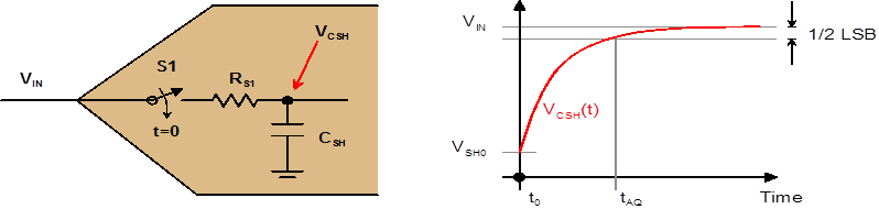
Figure 1: Charge distribution to settle signal

During the acquisition phase, there is a charge transfer from the input signal source to the ADC’s internal sampling capacitor, CSH. The VIN signal on CSH must settle to at least one-half the least significant bit (LSB) of the final value during the acquisition time, tAQ. Obviously, if the input source requires a longer settling time than tAQ, the residual voltage error across CSH at the end of tACQ will be greater than one-half the LSB, and the ADC output will be inaccurate.
But distortion is not merely an accuracy issue observed at some value of the input voltage. Distortion signifies a nonlinear relationship between the ADC’s input and output. In other words, the ADC transfer curve does not follow the equation of a straight line with constant slope and intercept over the ADC input range. So the question is, how can improper signal settling at the ADC input produce distortion or nonlinearity in the ADC response?
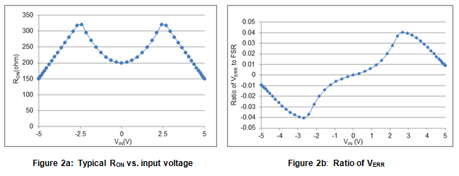
Generally, SAR ADCs have a switch-capacitor input structure with an integrated analog-sampling switch. The on-resistance of the switch, RON, has a nonlinear resistance with respect to the input signal voltage.
Figure 2a shows a typical RON vs. the input voltage curve of the complementary metal oxide semiconductor (CMOS) analog switch. The nonlinear on-resistance modulates the settling time constant so that the residual voltage error (VERR) between the input sinewave and the signal across the sampling capacitor at the end of tAQ is also nonlinear, as shown in Figure 2b. If the on-resistance is ideally constant, the error curve will be a straight line (shown in Figures 3a and 3b), and there will be no distortion in the ADC output.

Let’s take a look at one example with a settling problem. Industrial power-automation applications do not use front-end amplifiers with a SAR ADC due to cost and design-simplification reasons. Figure 4 shows a typical circuit.

Figure 4: Typical ADC circuit without a front-end amplifier
Figure 5 shows the AC performance of the circuit using the 16-bit, 8-channel ADS8568 SAR ADC with a front-end RC filter. A higher value of resistor and capacitor will get a better filter effect without using the active filtering in the circuit shown in Figure 4. However, this results in poor total harmonic distortion (THD), which is much worse than the -90dB spec in the ADS8568 datasheet. A second-order RC filter will make the performance much worse. The root reason is that the input signal, VS, has not settled properly on the sampling capacitor, CSH, during the ADC’s acquisition time.

Figure 5: Poor AC performance of the ADS8568 with a simplified front end RC filter
You can resolve this settling problem and improve performance by doing two things:
- Increase acquisition time by decreasing the sampling rate directly.You can calculate the real acquisition time with Equation 1, increasing tACQ_Real time by reducing the sampling rate, because the ADC datasheet specifies a maximum value for (conversion time) (Equation 2):

Figure 6 shows a refreshed test result with a second-order filter. The AC performance is significantly improved from the previous -65.46dBc to -92dBc THD with a 10Ksps to 1Ksps sampling rate reduction.
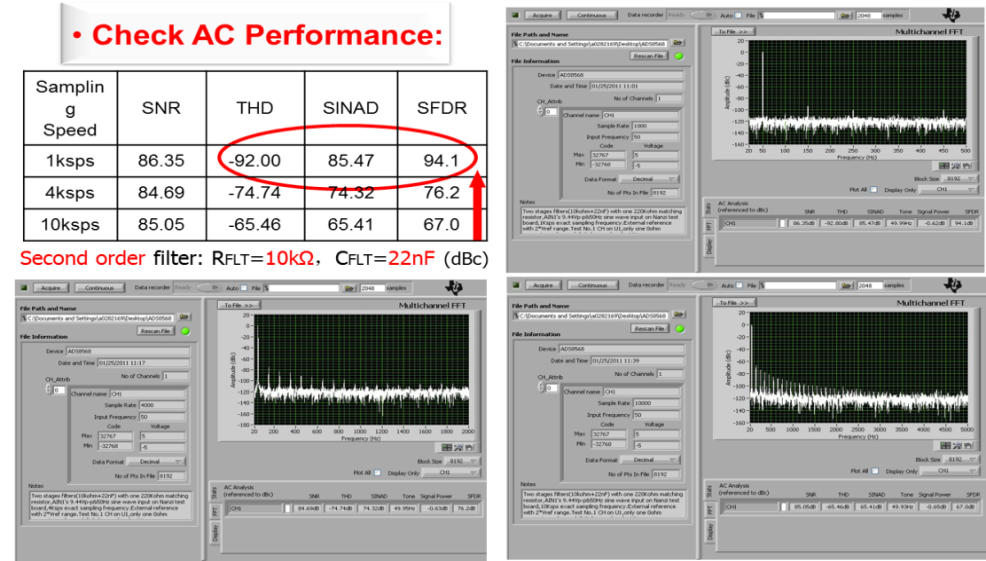
Figure 6: Test result with acquisition time increase
2. Speed up settling by reducing the order of the filter’s and decreasin XFLT/RFLT value. By reducing the front-end capacitor from 22nF to 820pF with the same 10kΩ resistor for a single-order filter, the THD improves from -70.97dBc to -96.88dBc with the same 10Ksps sampling rate. You can further THD performance to -103.61dBc for a slow 1Ksps sampling rate.
Figure 7 shows the measured results. Please note that there is a trade-off between settling-time improvement and the effect of RC filtering.
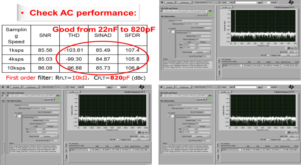
Figure 7: Test result with settling improvement
There are a variety of ways to resolve the settling challenge. However, these two methods are the simplest. Pay special attention to signal settling when designing a SAR ADC data acquisition system. Have you resolved the settling challenge in a different way? Leave a comment below on how you found success or what you tried that didn’t work.
Additional resources
- Learn more about designing with ADCs in the Data Converter Learning Center.
- See a SAR ADC applied in five TI Designs reference designs, optimized for various industrial data acquisition applications.
- Watch this short video to get to know TI’s SAR ADC portfolio.