

This post was co-written by Kunal Gandhi and Rahul Prakash.
Engineers may agree that one of the most anxious and stressful moments they face is when his or her design is back from fabrication and ready to be tested. While it is thrilling to see our concept or design work for the first time in the lab, sometimes we have to accept catastrophic failures, too.
In this blog post, we will focus on predicting system performance and avoiding failures. The term that immediately comes to my mind to avoid these failures is “simulation.” Currently, customers can model and simulate the majority of their analog signal chain components in SPICE simulation tools, except the digital-to-analog converter (DAC). With special SPICE models for Precision DACs, board engineers are no longer required to fully trust hand calculations before implementing actual hardware.
The SPICE models are available in two variants. One uses a simple n-bit wide parallel interface, as shown in Figure 1, which is compatible with all TINA-TI versions. The other model uses a serial SPI interface, shown in Figure 2, and is compatible with Industrial TINA-TI. Both variants include models for the important DC characteristics of the DAC and output amplifier such as offset error, gain error, output voltage swing to rail, temperature drift and quiescent current. Additional characteristics of AC parameters include slew-rate, settling time, power-on glitch and stability. The SPI interface model also completely replicates the digital interface and can be used to simulate the digital signal chain to the input of the DAC.
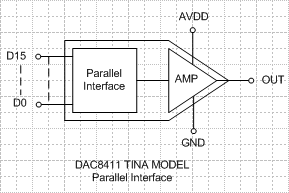
Figure 1 – DAC8411 Model (Parallel)

Figure 2 – DAC8411 Model (Serial)
Predicting and understanding how a DAC or op-amp will perform when driving a given load is an important aspect of any design. Let’s take a look at an example by simulating settling time with the DAC8411 SPICE model.
The left-side of Figure 3 shows a transient simulation of the DAC output with a code step from ¼ full-scale to ¾ full-scale. In this simulation the DAC is driving a 2kΩ resistive load in parallel with a 200pF capacitor – the same load used to specify settling time in the datasheet. The SPICE model accurately replicates the settling time of a typical characteristics curve from the datasheet, which is shown on the right side of Figure 3.

Figure 3 – DAC8411 Transient Simulation
But what if you need to drive a load that is different than the load specified in the datasheet? The left side of Figure 4 shows a simulation where the DAC output is loaded with a larger capacitive load of 20nF. In this case, the transient simulation shows considerable ringing, or oscillation, of the DAC output due to instability of the output amplifier with a larger capacitive load. The availability of a complete SPICE model helps catch this problem early so compensation components can be included in first prototypes.
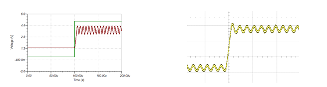
Figure 4 – DAC8411 Transient Simulation with 20nF capacitive load
Overall, the latest SPICE models for Precision DACs are aimed at giving engineers and designers a unique opportunity to simulate the entire analog signal chain, catch problems early and enable faster time to market. Check out these two TI Precision Designs to see the new DAC SPICE models in action:
- TIPD158 – Low Cost Loop-Powered 4-20mA Transmitter EMC/EMI Tested
- TIPD160 – Digitally Tunable MDAC based State Variable Filter
Feel free to leave any questions or comments about these new DAC SPICE models in the section below.
