

While working on a low-noise amplifier circuit for an upcoming TI Designs reference design, I was caught off-guard by some interesting behavior. Casually moving the printed circuit board (PCB) on my workbench caused the output voltage to jump! Fascinated, I decided to perform a highly scientific test: I tapped on the PCB repeatedly while observing the output voltage on an oscilloscope.

Figure 1: Circuit output produced by tapping on the PCB
The seven spikes in the output voltage shown in Figure 1 are the result of my tapping on the PCB. Many physical interactions with a PCB can cause the output of a circuit to change. For example, placing stress on the package of an op amp can change its offset voltage. However, this circuit was EXTREMELY sensitive to vibration, and op amps typically do not show this level of sensitivity. With this in mind, I turned my attention to the ceramic capacitors on the PCB.
Multi-layer ceramic capacitors are incredibly useful. They offer a unique combination of low equivalent series resistance (ESR) and equivalent series inductance (ESL) and high volumetric efficiency. Their construction consists of multiple layers of metal electrodes inside a ceramic dielectric material as shown in Figure 2.
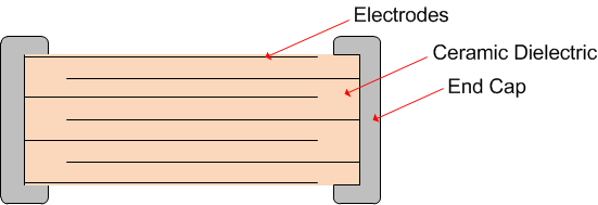
Figure 2: The typical structure of a multilayer ceramic capacitor
Barium Titanate (BaTiO3) is commonly used in the dielectric of ceramic capacitors because it can have a relative permittivity greater than 3000 [1]. Typically, as you shrink the physical size of a ceramic capacitor, increasing the capacitance requires a larger quantity of BaTiO3 to be used in the dielectric. Aside from high permittivity, BaTiO3 has another interesting property: it is highly piezoelectric. This makes it an excellent choice for piezoelectric microphones and guitar pickups!
The piezoelectric effect is the creation of a voltage due to an applied mechanical stress [2]. Figure 3 shows a ceramic capacitor soldered to a PCB. When downward pressure is applied (red arrow) the PCB deforms, causing the dielectric to be stretched or compressed by the end caps (blue arrows). When I tapped on my PCB, I applied a mechanical stress to the ceramic capacitors, causing a piezoelectric response in the dielectric and producing an output voltage.
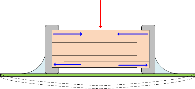
Figure 3: Mechanical stress on the PCB is coupled to the dielectric through the capacitor end caps
Piezoelectricity can be a major problem for electronics installed in high-vibration environments. In such applications the need for high capacitance, low ESR and ESL, and small size may lead an engineer to select a high-k ceramic capacitor (X7R, Y5V, Z5U, etc.), which contains a large percentage of BaTiO3 [3]. A common example is the capacitor placed on the reference input to an ADC. The circuit may work fine in the lab, where it isn’t being shaken vigorously. Once it is installed in an environment with vibration, significant errors in the ADC readings might appear. Power supply designers are also aware of the converse piezoelectric effect, where the ripple voltage across the capacitor causes it to “sing” or vibrate.
For my low-noise amplifier circuit, I chose to investigate a few different solutions to this problem:
- Soft-termination ceramics: These are ceramic capacitors with a flexible material inside the end-caps for stress relief. They were introduced for automotive applications, where PCB flexing can cause capacitors to fail.
- Tantalum capacitors: Tantalum capacitors reportedly do not exhibit microphonic effects [4]. However, they do have some disadvantages. They are polarized and typically have higher ESR and ESL than ceramics of similar size and capacitance.
- Film capacitors: Some customers have reported using film capacitors in high vibration environments with satisfactory results. The downside is that film capacitors are typically larger than ceramic or tantalum types and can be very expensive.
These solutions are component-level and don’t include possible modifications to the PCB, such as strain-relief cutouts. In my next post, I’ll test each of these capacitors in the same circuit and compare how sensitive they are to vibration.
Additional resources:
Read more about an ADC TI Designs reference design, TIPD115.
Download a datasheet on OPA211, a low-noise and low-power precision operational amplifier
Footnotes
[1] Kahn, M., Multilayer Ceramic Capacitors – Materials and Manufacture, http://www.avx.com/docs/techinfo/mlcmat.pdf
[2] Piezoelectricity, http://en.wikipedia.org/wiki/Piezoelectricity
[3] Caldwell, J., More about understanding the distortion mechanism of high-K MLCCs, http://www.edn.com/design/analog/4426318/More-about-understanding-the-distortion-mechanism-of-high-K-MLCCs
[4] Cain, J., Comparison of Multilayer Ceramic and Tantalum Capacitors, http://www.avx.com/docs/techinfo/mlc-tant.pdf


