

If you missed Part 1 in this series, here’s the background:
While working on a low-noise amplifier circuit I found that the ceramic capacitors on my printed circuit board (PCB) were exhibiting piezoelectric effects and ruining the otherwise extremely low noise of the circuit. This behavior is common in non-C0G type ceramic capacitors, and to remedy the situation, I decided to test three alternative capacitor types: soft-termination ceramic, tantalum and film. All of the capacitors tested were 2.2uF surface-mount types.
Using some items I found in my cubicle, I came up with a more controlled test than I used in Part 1. I had the idea that something impacting the PCB would be a good way to apply a repeatable stress to the capacitors. For example, a test mass could be dropped onto the PCB. Assuming that the test mass, drop height and impact location on the PCB remain constant, the stress applied to the capacitors in the circuit should be similar in all the tests. The disturbance caused in the amplifier’s output voltage could be used to compare how sensitive each type of capacitor is to vibration.
My test mass was an AA battery that would slide down a tri-corner ruler to hit a spot on the PCB free from components. Besides guiding the battery to the impact location, the ruler also made it easy to drop the battery from a consistent height above the PCB (2.25 inches for this test). The basic test setup is shown in Figure 1.
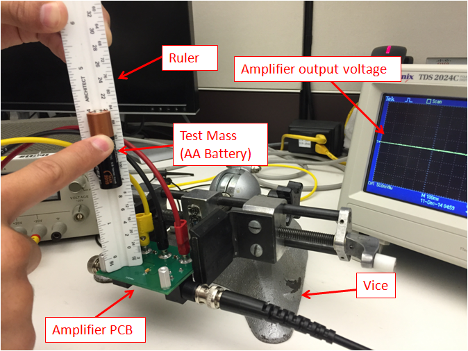
Figure 1: Test setup for comparing piezoelectric effects in different capacitor types.
The amplifier PCB was fixed in a vice and the input was shorted to ground ensuring that any large output-voltage disturbance was due entirely to capacitor piezoelectric effects. The output of the amplifier was connected to an oscilloscope set to be triggered when the amplifier voltage exceeded the typical noise floor. Figure 2 shows an example of the amplifier’s output when the battery impacts the PCB. For this waveform, X7R ceramic capacitors were used. Notice that the disturbance in the output voltage is large -- about 170mVpp!
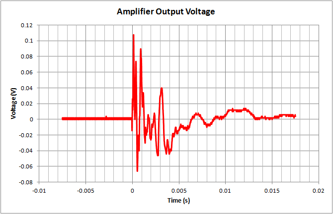
Figure 2: An example output voltage waveform when the battery impacts the PCB (ceramic capacitors, impact at t=0s).
The peak-to-peak measurement function on the oscilloscope was used to quantify the output voltage disturbance. For each type of capacitor, I performed five impact tests and then took the average of the runs. The results for each type of capacitor are shown in Figure 3.
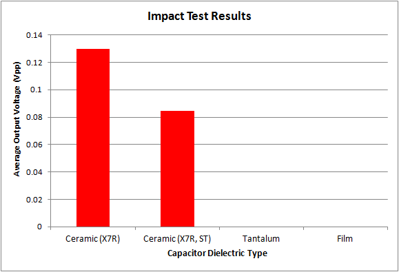
Figure 3: Average peak-to-peak output voltage of the amplifier from the impact test (by capacitor type)
I find these results interesting for two reasons.
1) Although the soft-termination ceramic capacitors (Ceramic X7R, ST) reduce the output voltage disturbance, it was not enough to be useable in my application. However, this amount of reduction might be enough in applications with lower gains or higher noise floors.
2) The tantalum and film capacitors showed absolutely no sensitivity to vibration! This is the real take-away from this testing, if you have an application that must be immune to vibration effects, such as low noise circuits in automotive environments, tantalum and film capacitors should be used.
Unfortunately, these types of capacitors also have their drawbacks. Film capacitors are expensive and typically are larger than ceramic or tantalum capacitors of the same value. Tantalum capacitors are polarized and will not be useable everywhere in a circuit. Tantalum capacitors also have higher ESR than similar ceramic types, but this may be overcome by placing C0G ceramic capacitors in parallel with a Tantalum capacitor. The right capacitor choice for your application depends on the requirements for cost, PCB area and the circuit performance. Armed with the knowledge from this blog series, you’re ready to build circuits that keep their composure, even in stressful situations!
Additional resources:
Learn how the TIPD147 works with low-noise design and noise measurement.
Read other blog posts about working with low noise amps, including Part 1 of today’s series.