

To describe delta-sigma modulator performance, manufacturers typically assume that the modulator is used with a particular low-pass digital filter. Many times, the type of filter selected is a sinc filter of order 3.
Figure 1 shows the frequency response of a typical sinc 3 filter.
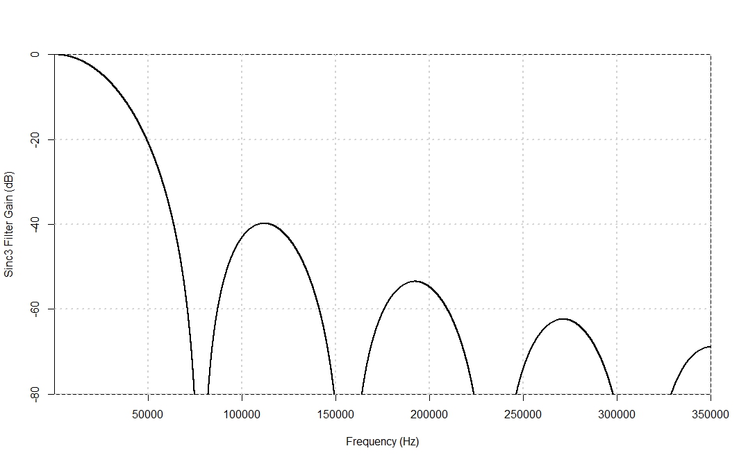
Figure 1. Frequency response of sinc3 filter running at 20MHz with OSR = 256
Sinc filters belong to a family of digital filters called cascaded integrator-comb (CIC) filters. CIC filters are used frequently with delta-sigma modulators because they have very efficient hardware structures that can be built using a relatively low number of digital gates compared to other filter architectures. Figure 1 uncovers the main tradeoff when using sinc filters: the filter structure is simple and inexpensive to implement, but the transition band of these filters is rather wide.
Often times, motor controllers and power inverters use acquisition systems like the one shown in Figure 2. There are many “knobs” that you can turn in order to configure the system. The main question is: How does each knob affect system performance?
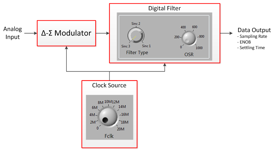
Figure 2: Simplified acquisition system using delta-sigma modulator and digital filter
To answer this question let’s examine the different variables of the system and how they interact.
The first relationship to consider is between the clock frequency (this frequency is used to run both the modulator and the digital filter) and the output data rate. Equation 1 below relates these two variables.
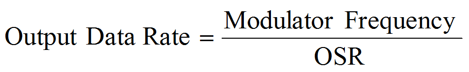
The oversampling ratio (OSR) variable in Equation 1 is a characteristic of the digital filter; it essentially dictates the level of decimation performed. In other words, the OSR tells us how many samples are taken in by the filter (at a ratio given by the clock frequency) per each sample put out by the filter (at a ratio given by the output data rate).
To get a good idea of how output data rate (in samples per second [SPS]) and OSR relate to each other, see Figure 3.
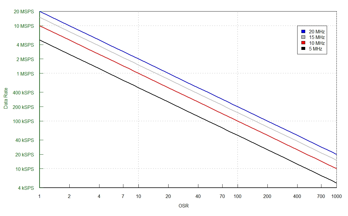
Figure 3. Sampling rate for various modulator frequencies
For example, a system running from a 20MHz clock and using an OSR of 256 yields filtered data at 78,125SPS, whereas a system using a 10MHz clock and OSR of 10 yields filtered data at 1MSPS.
Suppose that we decide to use a 20MHz clock and are interested in the level of performance we can get out of the system. Figure 4 shows a graph that helps answer this question.

Figure 4: Effective number of bits and signal-to-noise ratio as a function of filter type, OSR and data rate for a system running at 20MHz
Figure 4 displays two key metrics of system performance. Equation 2 below relates the effective number of bits (ENOB) and signal-to-noise ratio (SNR). ENOB and SNR provide a quick snapshot of the acquisition system effectiveness. As Figure 4 illustrates, OSR and filter type play a crucial role in system performance; the higher the OSR, the more precise the system becomes. Figure 4 also clearly shows that the price paid for higher precision is a lower data rate.

The one missing part of the performance puzzle is whether latency exists in the signal chain. As you can imagine, it does! The more aggressive filtering you choose (by selecting a higher-order filter or by increasing the OSR), the more latency in the system.

Figure 5: Step input response: settling time of a system running at 20MHz for different filter types
Input Response: Settling time of a system running at 20 MHz for different filter types
As you can see in Figure 5, systems that yield high precision results (by choosing a higher-order filter or by increasing the OSR) take a longer time to settle in the face of a step input. This longer time to settle is evidence of the longer latency present in the system.
System designers always face performance trade-offs; a system like that shown in Figure 2 is no exception. The trade-off that such systems present is this:
- On the one end of the spectrum, you can choose a high-precision system with a high SNR and high ENOB. To achieve that, turn both the filter-order knob and the OSR knob high. The trade-off is a lower output data rate and longer latency.
- On the other end of the spectrum, you can choose a high-throughput system that settles quickly. To achieve that, turn both the filter-order knob and the OSR knob low. The trade-off is lower SNR and ENOB.
Fortunately, plenty of room exists between these extremes, allowing you to choose a system that fits your particular application needs.
Additional resources:
Learn how to use delta-sigma modulators for isolated high-voltage measurements
How delta-sigma ADCs work, Part 1 by Bonnie Baker, Analog Applications Journal
How delta-sigma ADCs work, Part 2 by Bonnie Baker, Analog Applications Journal