

As a newly hired employee recently out of college, previously known as “John the intern”, I thought my learning days were over. However, I quickly found out that is not the case and had a lesson on electro-static discharge (ESD) diodes of a device and the unintended effects they may cause in an application.
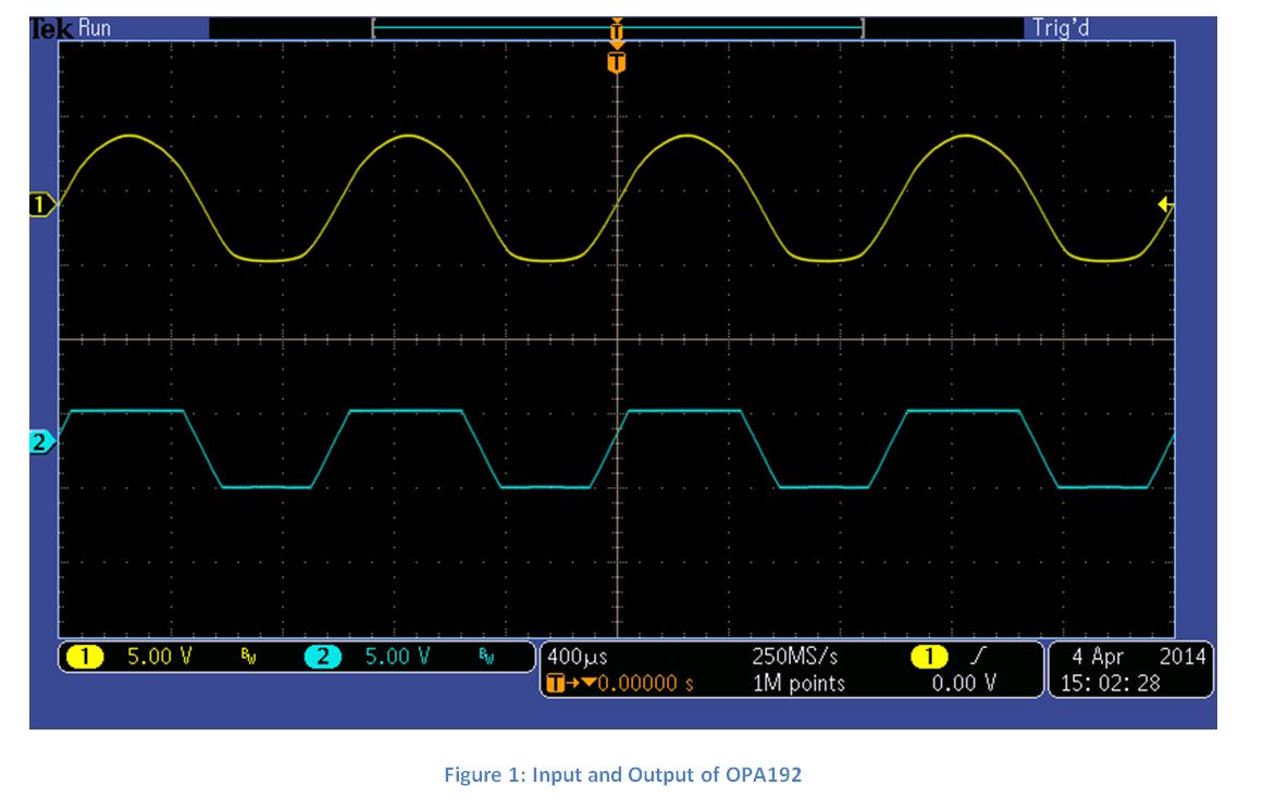
I needed to do some testing on the OPA192, so I grabbed my circuit board, headed to the lab and connected everything up. I noticed some very odd behavior when I observed the output on the oscilloscope. The device was in a unity gain configuration, so I expected the output to be equal to the input. Figure 1 shows the input (channel 1) and output (channel 2) of what I saw.
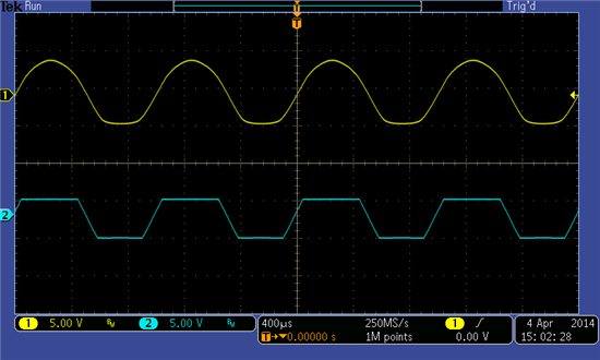
Figure 1: Input and Output of OPA192
After some troubleshooting, I realized I made a rookie mistake. I forgot to turn on the power supplies! This got me thinking, how can there be an output without powering the device?
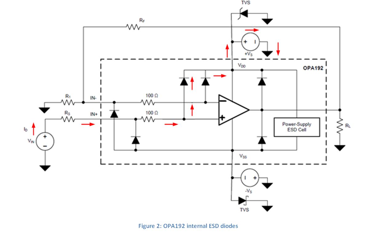
I researched this phenomenon and found Figure 2 in the OPA192 datasheet that shows the internal ESD diodes of the device.
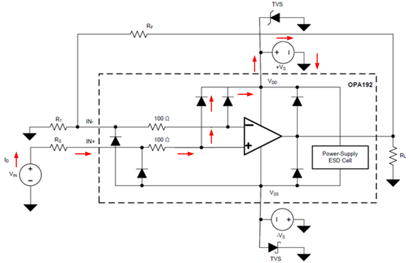
Figure 2: OPA192 internal ESD diodes
I found that if an input signal is greater than the supply voltage by approximately one diode drop then the positive supply diode would conduct and route current around the device and to the power supplies. With the power supply turned off, all that is present is the internal impedance of the supply. Figure 3 shows a simplified version of Figure 2 with an equivalent model of the power supplies.

Figure 3: Simplified OPA192 schematic with equivalent power supply model
Routing the input signal to the supply will create a voltage drop across the impedance of the power supply and this will cause a voltage to be present on the power supply pins. Table 1 shows the voltage measured at the output, positive supply and negative supply for different input voltages.
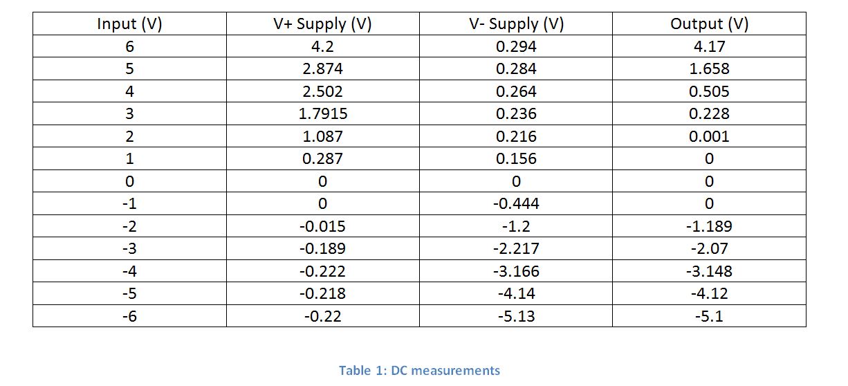
As you can see, with a positive voltage at the input the V+ supply has a measurable voltage. This is because ESD diode D1 is conducting and creating a voltage on the positive power supply. Similarly, with a negative input, a voltage is present at V- supply because ESD diode D2 is conducting. The voltage at the supplies turns on the internal transistors of the device and it begins to operate as it would with the supplies turned on. This is why I saw a distorted sine wave at the output with no power to the device.
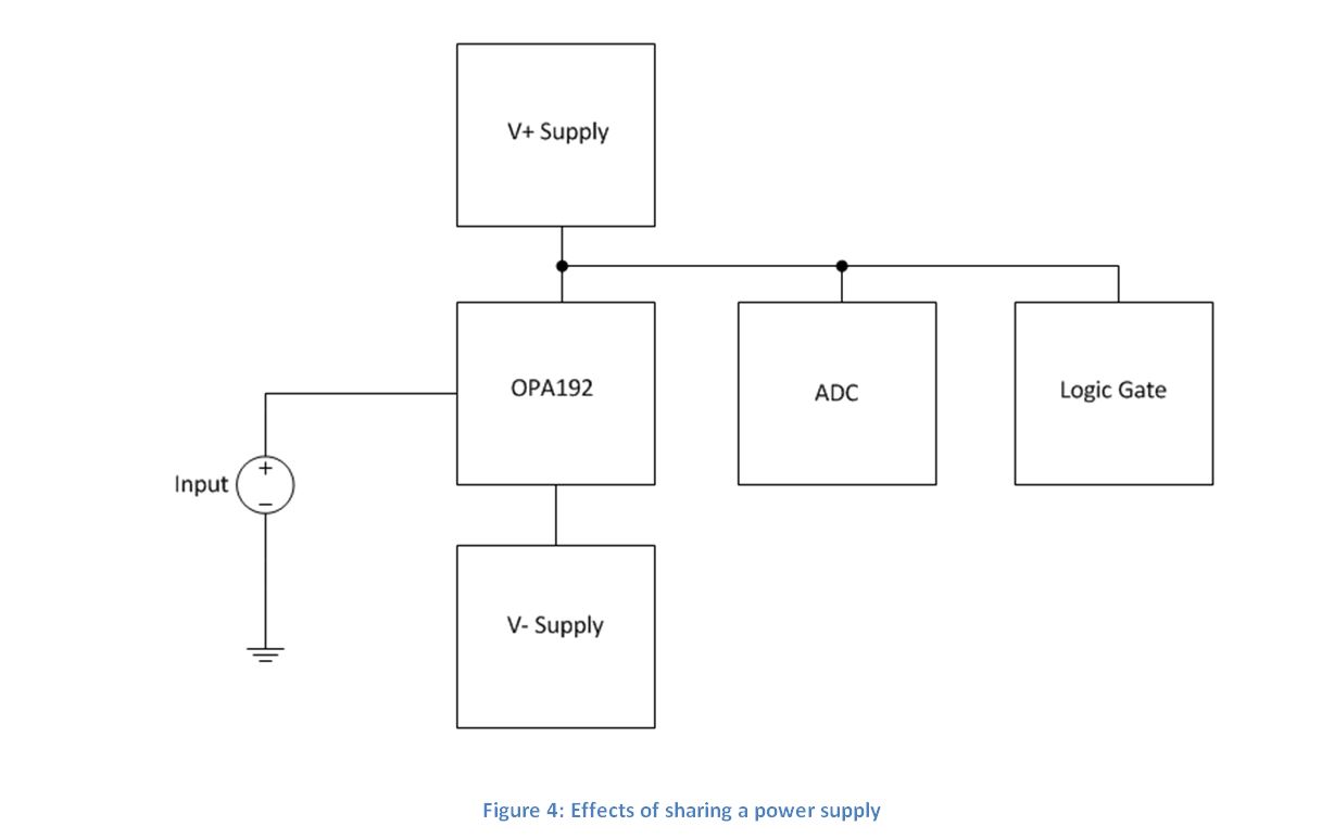
In a typical system, there are multiple devices that share the same power supply. These devices may turn on unexpectedly because of the voltage at the power supply pins caused from turning on the ESD diodes of the device. Figure 4 shows a block diagram of how sharing the same supply can potentially power other devices, such as analog to digital converters (ADC) or logic gates.
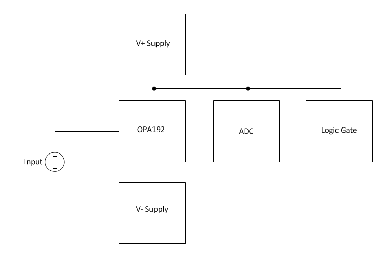
Figure 4: Effects of sharing a power supply
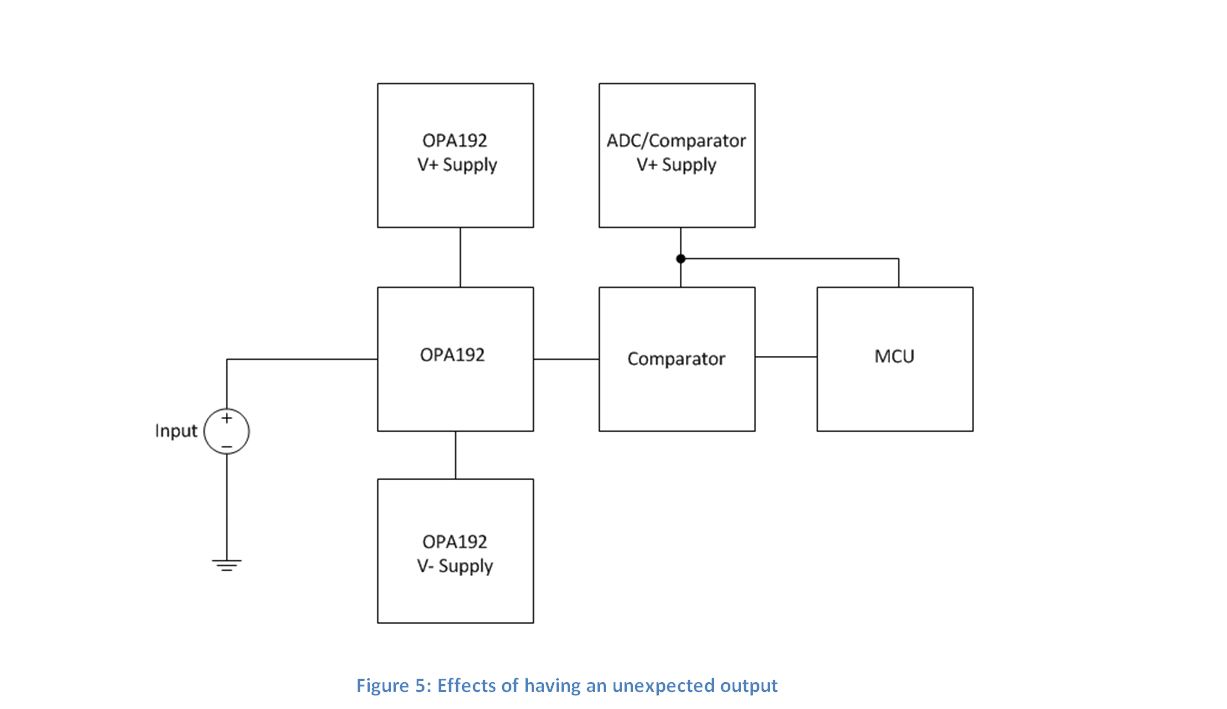
Furthermore, having an unexpected output similar to the one shown in Figure 1 is just as problematic. The output might be connected to a comparator that interfaces with a microcontroller (MCU). If the comparator and MCU are powered with a separate supply, the output of the amplifier could cause the comparator to output false data to the MCU. Figure 5 shows a block diagram of how having an unwanted output to a comparator can cause a MCU to receive false data.
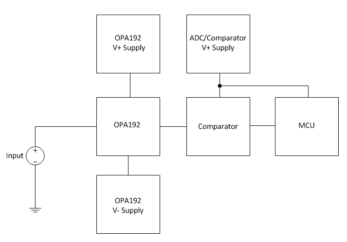
Figure 5: Effects of having an unexpected output
Both of these situations will give false results in the system, which can cause the entire system to fail. The effects of this vary but can be as drastic as a car turning off while driving or disabling a piece of medical equipment.
If your design can have an input with the device not powered, you may want to consider placing a switch between the input signal and input pin of the device. Eliminating any possible input to the device will prevent the internal ESD diodes from conducting and powering the device (and possibly other devices) with the input signal.


