

Noise and distortion are two common enemies for engineers designing precision analog systems. But when looking at total harmonic distortion and noise (THD+N) figures in an op amp datasheet, it may not be immediately clear which enemy you’re battling: noise or distortion?
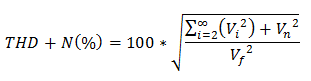
“Noise” describes the random electrical signals produced by the amplifier. “Distortion” refers to unwanted harmonics introduced by the amplifier. A harmonic is a signal at an integer multiple frequency of the input signal. The total harmonic distortion and noise specification quantifies these factors by comparing the level of distortion harmonics (Vi) and the RMS noise voltage (Vn) to the level of an input signal (Vf) by using this equation:
This curve, from the OPA316 datasheet, shows the measured THD+N over frequency for multiple configurations and output loadings. Unfortunately, we don’t immediately know if noise or distortion harmonics have a greater effect on the THD+N. To gain some insight on this, we can calculate the noise contribution to the measurement.

Figure 1: THD+N vs. frequency of the OPA316 in multiple configurations
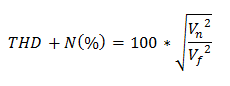
First, we simplify the THD+N calculation to remove the distortion term:
We can approximate the RMS noise voltage of a basic op amp circuit with the equation:
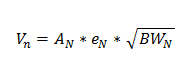 AN is the “noise gain”, eN is the op amp broadband voltage noise spectral density, and BWN is the bandwidth over which noise is measured. Noise gain, or the gain the amplifier applies to its intrinsic noise, is always measured from the non-inverting input of the op amp. This is straightforward when the op amp is used as a non-inverting amplifier; the signal gain and noise gain are the same. However, for inverting amplifiers, the noise gain will be one plus the magnitude of the signal gain. For example, an inverting amplifier with a signal gain of -1 has a noise gain of +2.
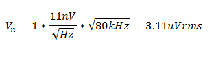
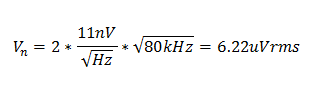
The OPA316 has a broadband input voltage noise spectral density of 11nV/√Hz, and the measurement bandwidth is specified as 80kHz. For the non-inverting amplifier (G = +1), the approximate RMS noise voltage is:
 For the inverting amplifier (Gain = -1), the RMS noise voltage is:
Now, the noise contribution to the THD+N measurements for the two configurations can be calculated using the output amplitude information given below the graph.
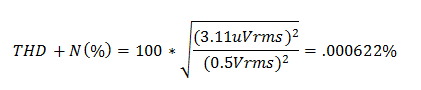
Non-Inverting (G = +1):
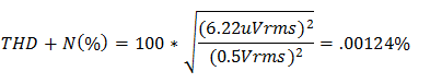
Inverting (G = -1):
Notice that these calculated values correspond very closely to the measured THD+N at low frequencies (<500Hz). Here the measurement is determined almost entirely by the noise of the op amp. The THD+N measurement is flat at the noise dominated frequencies because the frequency of the input signal does not affect the noise voltage.
Likewise, at low signal amplitude, the THD+N measurement is dominated by the noise contribution. Figure 2 shows the THD+N vs. output amplitude for the OPA316, measured at 1kHz. Below 300mV the two curves have a constant slope. The RMS noise is constant, regardless of input signal amplitude, so increasing the signal amplitude improves the THD+N measurement. For example, in the noise dominated region of the curve, doubling the output amplitude will cut the THD+N value in half.

Figure 2: THD+N vs. output amplitude at 1kHz of the OPA316 in multiple configurations
On the other hand, the amplitude of distortion harmonics may change with signal amplitude. Once the curve deviates from a constant downward slope, we know that distortion harmonics are affecting the THD+N measurement.
Circuit design for low noise often has the unwanted consequence of increasing distortion. A non-inverting op amp with low-value feedback resistors may provide exceptionally low noise, but the additional loading and common-mode voltage can increase high frequency distortion. Knowing if noise or distortion is limiting your system performance is crucial to finding an engineering solution. Armed with some basic hand calculations, and an understanding of datasheet THD+N graphs, you can quickly determine the culprit.
Additional resources:
Learn how an op amp instrumentation amplifier’s offset voltage changes with gain.
See which instrumentation amplifiers CMRR doesn’t change with gain.
Related reference designs from TI Designs – Precision library:
