

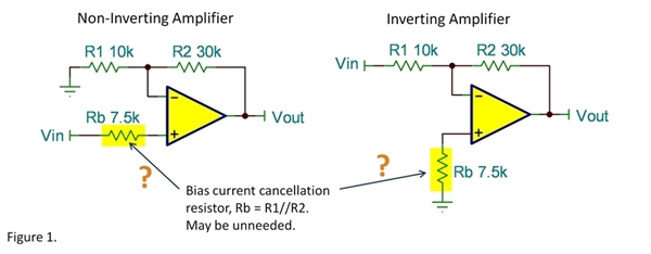
Last week we reviewed the use of an input bias current cancellation resistor to balance the source resistance at the two inputs of an op amp. The conclusion was that this practice is often not necessary and may even be detrimental. This discussion builds on the previous blog so you may want to review it, first.
I ended last week saying that there are certain op amps for which this practice is definitely not recommended. These are amplifiers with bipolar input transistors (BJTs) that have internal input bias current cancellation. They have current sources, I1 and I2 that supply base current for the input transistor pair. These currents are derived by mirroring carefully matched base currents into the op amp’s input terminals.
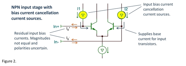
While these currents are accurately matched to the base current of the input transistor (typically within a few percent), they are not perfect. They leave a small residual input bias current that could be positive or negative. This residual current may be quite different on the two input terminals. They may even be opposite polarities. Any possible benefit from matching source resistance (as in figure 1) relies on nearly matching input bias currents. Internal input bias current cancellation renders this practice useless.
Which op amps have input bias current cancellation? Data sheets sometimes don’t make this feature apparent. The effects are generally revealed, however, in the details of the input bias current specifications.
Figure 3a shows the input bias current specification for the OPA209, a low noise op amp with input bias current cancellation. Note that the input bias current is preceeded by a ± symbol to indicate that current could flow in either direction, your first hint. Also, note that the specifications for input offset current are are the same magnitude as the input bias current (actually identical on this op amp). These specifications reveal that this device has internal input bias current cancellation.
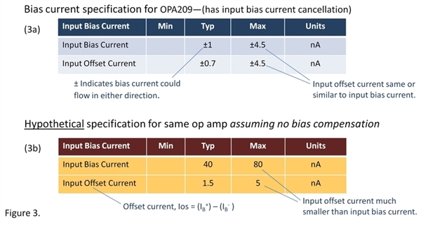
Figure 3b shows a hypothetical specification for the OPA209 assuming it did not have bias current cancellation. Note the much larger input bias current. And now, the input offset current is much smaller than input bias current because the two input bias currents are nearly equal. Depending on the circuit and application, this hypothetical op amp might benefit from the use of a bias current cancellation resistor as shown in figure 1.
Internal input bias current cancellation is generally found on precision and low noise op amps with bipolar (BJT) input transistors—ones that would otherwise have uncomfortably high input bias current. Internal cancellation makes these amplfiers useful in a wider range of circuits.
Do you ever design circuits that rely on a known polarity of input bias current? It wouldn't be wise with these cancelled-input devices, right?
Comments welcome and thanks for reading,
Bruce

