

The input capacitance specifications of op amps are often confused or ignored. Let’s clarify how these specs can best be used.
Stability of an op amp circuit can be affected by input capacitance at the inverting input by causing phase shift—a delay of the feedback reaching the inverting input. The feedback network reacts with input capacitance to create an unwanted pole. Scaling the impedance of the feedback network in relation to the input capacitance is an important step to assure a stable amplifier circuit. But which capacitance matters—differential?… common-mode?… both?
The input capacitance of an op amp is generally found in an input impedance specification showing both a differential and common-mode and capacitance.

Input capacitance is modeled as a common-mode capacitance from each input to ground and a differential capacitance between the inputs, figure 1. Though there is no ground connection on an op amp with dual supply voltages, consider the common-mode capacitances as connected to the V- supply terminal, the AC equivalent of ground.
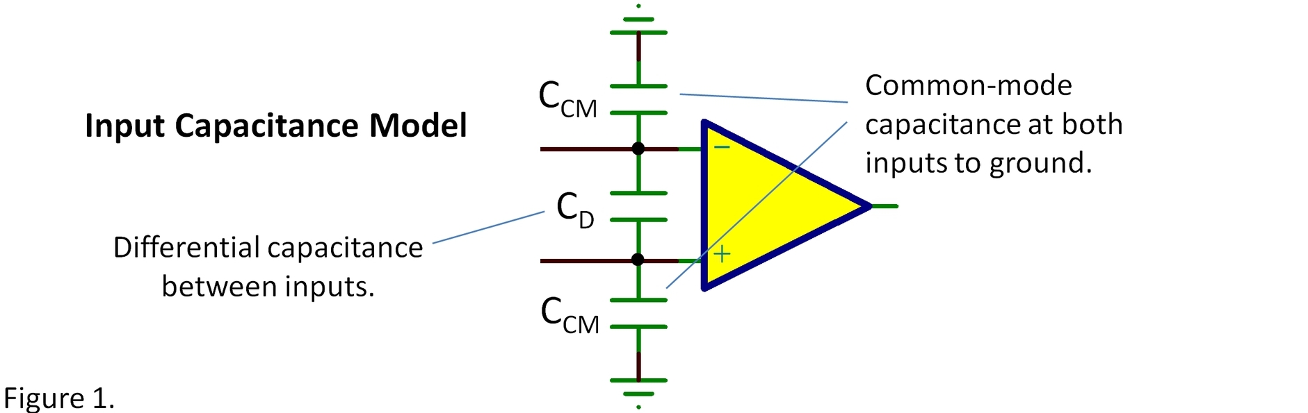
At high frequency where stability is a concern, the op amp has little open-loop gain and there is substantial AC voltage between the two inputs. This causes the differential capacitance to combine with the inverting common-mode capacitance to alter the phase of the feedback signal. So add the two capacitances that connect to the inverting input. Include an estimate of stray wiring capacitance (perhaps around 2pF). This total capacitance reacts with the parallel impedance of the feedback network (R1//R2) to create a pole.
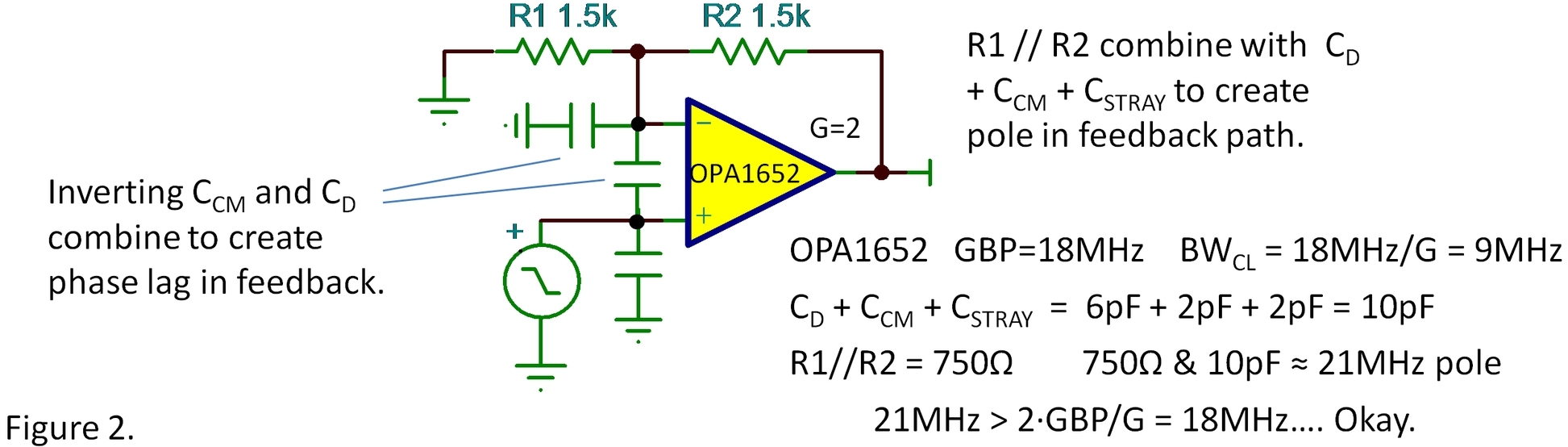
A guideline: The frequency of this pole should be should be greater than two-times the closed-loop bandwidth of the amplifier. A pole at two-times the closed-loop bandwidth will reduce the phase margin of the circuit by approximately 27°. This is generally okay for most circuits in a closed-loop gain of two or greater. Applications with critical settling requirements or capacitive load may require even greater margin. Reduce the feedback network impedance or consider adding a capacitor across the feedback capacitor, R2.
Today’s “general purpose” op amps often have wider bandwidths, from 5MHz to 20MHz and more. Feedback network resistances that may have been okay with 1MHz op amps can now create problems, a reason to be diligent in checking stability of your designs.
SPICE simulation is very helpful in checking sensitivities to input capacitance and feedback impedance and good op amp macro-models accurately model input capacitances. A transient response check with a 1mV input step should not cause excessive overshoot and ringing. But remember, reality always trumps guidelines and simulations. This is the type of circuitry may require fine tuning in a final circuit layout.
This discussion relates to several previous blogs. Some are linked in the text above. Here’s a summary of ones that you may find helpful…
- Why Op Amps Oscillate—an intuitive look at two frequent causes
- Taming the Oscillating Op Amp Capacitance at the inverting input.
- SPICE It Up! … but does Bob Pease say no? Is SPICE a crutch or a tool?
- SPICEing Op Amp Stability Using SPICE to check stability of op amp circuits.
- PCB Layout Tricks Includes a tip on minimizing stray capacitance at the inverting input.
- TINA-TI A free SPICE simulator from TI.
Thanks for reading and comments are welcome.
Bruce email: thesignal@list.ti.com (Email for direct communications. Comments for all, below.)
Other interesting “The Signal” Topics.
-

Bruce Trump
-
Cancel
-
Vote Up
0
Vote Down
-
-
Sign in to reply
-
More
-
Cancel
Comment-

Bruce Trump
-
Cancel
-
Vote Up
0
Vote Down
-
-
Sign in to reply
-
More
-
Cancel
Children