

Welcome to “The Signal,” a technical blog focusing on analog signal processing circuits.
Op Amps used as Comparators—is it okay?
Many of you (and I, too) occasionally use an op amp as a comparator. Often, this is when you only need one simple comparator and you have a “spare” op amp in a quad op amp package. The phase compensation required for stable op amp operation means that it will be very slow as a comparator, but if speed requirements are modest, the op amp may suffice. We get sporadic questions about this use of an op amp. Some work okay… some don’t operate as expected. Why?...
Many op amps have voltage clamps between the input terminals, most often implemented with back-to-back diodes (sometimes with two or more diodes in series). These diodes protect the input transistors from reverse breakdown of their base-emitter junctions. With many IC processes breakdown would occur at approximately 6V differential input and could significantly alter or damage the transistor. With the NPN input stage shown below, D1 and D2 provide the protection.
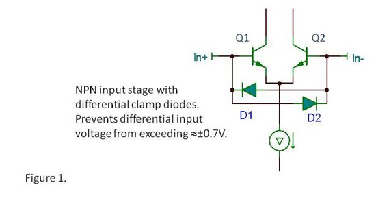
In most common op amp applications you have near zero volts across the inputs and never turn on these diodes. But clearly, this protection can be a problem for comparator operation. You have a limited differential voltage range (0.7V, or so) before one input will tug on the other, pulling its voltage in an unexpected manner. This may not rule out its use as a comparator but it would require some careful consideration. In some circuits, it may be totally unacceptable.
The problem is that we (and other op amp manufacturers) have been inconsistent in communicating the presence of these clamps. Even when we do, we may not explain or interpret the message. Maybe we should say, “be careful if used as a comparator!” The authors of data sheets often just assume that you are going to use an op amp as an op amp. We recently held a meeting in our Tucson product group and resolved that we would communicate this more clearly in the future. But what about all the op amps already out there? Here are some guidelines that may help:
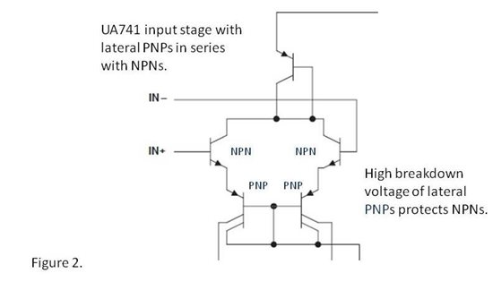
In general, op amps with bipolar NPN transistors have input clamps. Examples would be OP07C, OPA227, OPA277, etc. An exception is the old uA741 which has NPN input transistors but additional lateral PNPs in series that provided inherent protection for the NPNs.
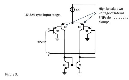
General purpose op amps with lateral PNP input transistors generally do not have input clamps. Examples include LM324, LM358, OPA234, OPA2251 and OPA244. These op amps are generally “single-supply” types, meaning that they have a common-mode range that extends to the negative supply terminal or slightly below. They can often be identified as the input bias current is listed as a negative number indicating that input bias current flows out of the input pins. Note, however, that high speed op amps using PNP inputs generally have input clamps as these are vertical PNPs with lower breakdown voltage.
JFET and CMOS amplifiers that operate on higher voltage (greater than 20V, or so) may or may not have clamps. It’s an iffy proposition that requires more checking. The characteristics of the process and the particular transistors used determine whether clamps are present internally.
Most low voltage CMOS op amps do not have clamps. There is a special exception for auto-zero or chopper types that may have behaviors that look like clamps.
The bottom line... if you consider using an op amp as a comparator, use caution. Glean what you can from the data sheet, including comments in the applications section. Validate its behavior in a breadboard or prototype, checking for influence of one input voltage on the other. Don’t rely on a SPICE macromodel. Some macromodels may not include extra components to model the clamps. Furthermore, other behaviors that can arise when you bang an op amp from rail to rail may not be accurately modeled. If you’re in doubt, ask us on our E2E forums.
Can differential clamps affect standard op amp circuits? Op amps should have nearly zero voltage across the inputs, right? More on this next week.
Thanks for reading,
Bruce
-

Yukang Wu
-
Cancel
-
Vote Up
0
Vote Down
-
-
Sign in to reply
-
More
-
Cancel
Comment-

Yukang Wu
-
Cancel
-
Vote Up
0
Vote Down
-
-
Sign in to reply
-
More
-
Cancel
Children