

When providing a sensitive amplifier input terminal to the outside world, designers wonder what someone might connect or how it might be treated. Will it be treated with care… or could they carelessly plug it into the AC mains? We all would like to make our equipment robust, able to sustain the most brutal treatment. How to protect against Electrical Over-Stress (EOS)?
The OPA320 is typical of most op amps; absolute maximum ratings describe maximum power supply voltage and maximum input terminal voltage and current, figure 1. The accompanying note indicates that if you limit input current, you don’t need to limit the input voltage. Internal clamp diodes are safe to ±10mA. But limiting the current with high voltage overloads can require a high series input resistance, increasing noise, decreasing bandwidth and possibly creating other errors.

The clamp diodes begin conducting when the input voltage exceeds the rails by 0.6V, or so. Many devices can typically tolerate higher current but the forward voltages increases dramatically, increasing the chance of damage.
You can greatly improve tolerance to higher fault currents and increase the level of protection by adding external diodes. Common signal diodes such as the ubiquitous 1N4148 typically have a significantly lower forward voltage than the internal clamp diodes. In bench tests, I found that a variety of 1N4148 diodes in our bin all had forward voltages at least 100mV lower than the internal clamps on our amplifiers. Connected in parallel with the internal ones, the majority of fault current will flow in the external diode.
Schottky diodes have an even lower forward voltage and may provide improved protection. The disadvantage—they tend to be very leaky. Reverse leakage current specifications are generally a microamp or more and that’s at room temperature. Leakage rises with temperature.
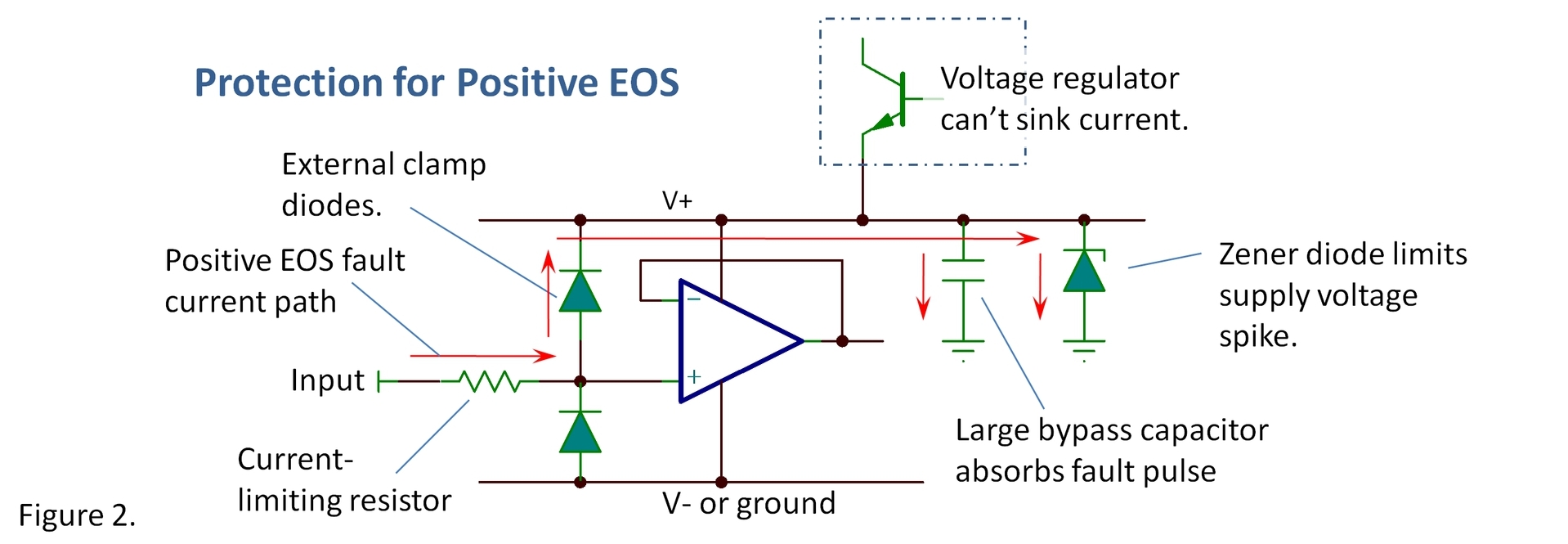
Beware… you need a solid power supply voltage. Clamp diodes, whether internal or external, rely on a relatively steady power supply voltage to limit the stress. If the offending fault pulse can dump enough current into the power supply rail, raising (or lowering, on V-) the power supply, it can over-stress the supply voltage terminal, figure 2. A typical positive linear regulator cannot sink current and can’t be relied upon to hold a steady voltage. Larger supply bypass capacitors can help absorb a large pulse of fault current. Sustained fault current may require a zener clamp on the power supply. Use a zener just above the maximum power supply voltage so that it only conducts during a fault. Note that on ± supplies you would need equivalent protection on the negative side.
These measures still may lead to voltages beyond the rated max values, but here’s the point: Absolute max ratings are generally very safe; damage at these voltages or current is extremely unlikely. There is generally a significant margin beyond these ratings where damage is still quite unlikely (but no promises). It’s much easier to clamp to a couple volts beyond these ratings and you are still likely to achieve high survival rate. In many cases, the goal is to dramatically improve survival rate without great expense or performance compromises.
It’s not possible to recommend a one-size-fits-all solution or assure that a particular protection scheme will meet your needs. Application details vary widely. Amplifiers differ in their sensitivity and the needed level of protection differs dramatically. It may require some creativity and may need to become your own best expert. Sacrifice some amplifiers with some torture testing, if necessary. As always, you are also welcome to ask advice on our E2E forums.
Surely some of you have valuable tricks to share. Help us all by adding your suggestions in your comments below. Also, check out some related links below.
Thanks for reading,
Bruce thesignal@list.ti.com
Index to all The Signal blogs.
Many of our instrumentation amplifiers have internal protection to ±40V even with no power supply voltage. For example, check out INA826.
TI makes very robust protection devices that are primarily intended for ESD protection of digital interfaces on computer and consumer equipment.
Example: TPD1E10B06 Protection Device Selector
These are fast-acting clamps that connect to ground and are selected to turn on a specified voltage, like a zener diode. For precision analog inputs the issue is, again, relatively high leakage currents (100nA range). Still, they may very useful in some applications.

