This thread has been locked.

If you have a related question, please click the "Ask a related question" button in the top right corner. The newly created question will be automatically linked to this question.

CC2640R2F: CC2640R2 Custom Board Power Saving issue

Part Number: CC2640R2F

Hi ,

To remind the general perspective of the project, I am using custom board with CC2640R2FYFV which is BGA package. The aim of the project provide a constant current, make one of the GPIO pin HIGH and read the one of the ADC pin and make them in periodic. I used the BLE 4.2  simpleperipheral project. To read the adc value periodically I used the TI's Document  To generate constant current and make one of the GPIO HIGH, I used the Sensor Controller Studio then added the necessary files into CCS.  HIGH GPIO pin is the positive supply the Opamp that is in the my custom board, consant current is to negative pin of the Opamp and ADC pin is to read the output of the OPAMP and sent it to mobile phone via bluetooth. I want to do these four steps for 3 seconds and sleep for 7 seconds. So, IC should be in the active mode for 3 seconds and sleep for 7 seconds. I did this in the PerformPeriodicTask. Current version of the code does the work how I want properly but there are some issues that I will explain. 

It has been long time but various problems in each step. To remember the issue this is the link I could not success to set the board files as you instructed with my custom board. I tried to modify to board files by using LAUNCHXL files although no error It never advertises.

Board files are still with CXS files as I show this in link. The latest situation was that code was working when it is debugging but when I terminate and turn off the power then turn on the power It does not advertise again. Then I remove the POWER_SAVING from the Project -> Properties -> Predefined Symbols, I could flash the code both on CCS and Flash Programmer 2. It was good news but current consumption becomes 3.4 mA continously which is too high. It is same for all the time. When POWER_SAVING is defined in the Predefined Symbols and without terminating, for 3 seconds current consumption is 1.5 mA and 1.3 mA for the remaning 7 seconds. It could be acceptable but It does not flash both from CCS and Flash Programmer 2. 

So what do you recommend to able to flash the code and decrease the current consumption ? 

Regards,

I attached the both CCS and SCS files. It would be good if you could examine the codes ? 8311.simple_peripheral_cc2640r2lp_app.zip

  • Hi,

    The POWER SAVING should be defined. I suggest you try your current consumption measurements using the launchpad, so you don't experience the issues with custom board.

    Also, you can't use digital multimeter to measure current because the current is not steady. It is recommended to use DC power analyzer.

    With your issues with your custom board, not advertising I suspect you have issues with power. But also it could be a code issue.

    -kel

  • Hi,

    As mentioned by , the POWER_SAVING symbol should always be defined as it ensures the power driver sets the device in the lower power mode possible.

    Best regards, 

  • Hi Markel,

    Thanks for your quick answer.

    I used the Launchpad as you suggest. As I mention, POWER_SAVING is defined and UART DISPLAY things are disabled as you did in the your youtube video series. Also I set the board files as you instructed with LAUNCHXL files. So this time current consumption for 3 seconds is is 0.73 mA and 0.19 mA for 7 seconds which are too high to compared the datasheet values.

    I use the digital multimeter which is high quality Fluke that you mention in another threads and oscilloscope for double checking. The results are so close I think no problem on measurement side. 

    With your issues with your custom board, not advertising I suspect you have issues with power. But also it could be a code issue.

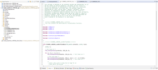
    For these sentences, What kind of power issues can it be ? I thought something in the POWER_SAVING definiton prevent to flash the code. Because after disabling the POWER_SAVING, I could flash the code to my custom board. It can also arised from the board files. Because board files for my custom board are not exactly same with Launchpad. The board files that I used like in the screenshot. As you can see, CC2640R2DK_CXS.h and CC2640R2DK_CXS.c are for my custom board but CC2640R2_LAUNCHXL_fxns.c is for the Launchpad and there are flash related codes in the CC2640R2_LAUNCHXL_fxns.c file.

    Regards,

  • Hi Clement,

    Thank you.

    Defining POWER_SAVING prevent code to flash. I am trying to find what cause that problem. Do you have any idea about it ? 

    Regards,

  • Hi,

    The launchpad can achieve low power standby and shutdown current according to datasheet.

    Hardware modification would be that the launchpad is battery powered and all jumpers removed.

    Firmware modification needs to be configured for low power. One modification would be disable UART. 

    High end Fluke multimeter can measure CC2640R2F average standby current. I have done this before.

    Issues with power, I mean with power circuitry.

    It is early for me to say that CXS board files would cause issues. I don't have experience with 2.7mm CC2640R2F. But, I only use the launchpad board files as base reference for custom boards because it works with latest SDK.

    I suspect you have an issue with your custom board circuitry. I suggest you work with the hardware designer to resolve your issue 

    -kel

  • Hi Markel,

    I have sent the files to review to TI engineers. After their feedback, I will tell you. But I can say that the only component on the custom board is one low power OPAMP except IC. Supply current of the OPAMP is 345 nA. It cannot cause the high current consumption but we will be sure after hardware engineer's feedback.

    I will try to decrease the current consumption in Launchpad with firmware modification and I will try to modify the board files with LAUNCHXL board files on my custom board. Because I think wrong modification in board files causes not flashing with POWER_SAVING definition.

    Regards,

  • Hi Markel,

    I have watched your BLE Peripheral Current Consumption video. In this video, did you shutdown the program periodically or for once ? I tried the things what you did but I got the error from this line. Error is "ButtonTableWakeUp" is undefined. 

    PINCC26XX_setWakeup(ButtonTableWakeUp);

    Where did you define the ButtonTableWakeUp ? You did not show in the video. Without the definition of "ButtonTableWakeUp", program goes shutdown and it never wakes up.

    I am planning to do ADC Reading and Sensor Controller stuff in 3 seconds and shutdown for 7 seconds. Is this possible ?

    I could disable the UART related. For now, current consumption for 3 seconds is 0.73 mA and 7 seconds 0.19 mA. If I can decrease the current from 0.19 mA to 1 uA it would be perfect.

    Regards,

  • Current values are for Launchpad.

  • Hi,

    I just placed the ButtonTableWakeUp on top of SimplePeripheral_Init().

    I ported the pin shutdown example program to simple peripheral example program.

    -kel

  • Hi Markel,

    I also ported the pinShutdown program to simpleperipheral. I defined the ButtontableWakeUp on top of SimplePeripheral_Init() and added the PINCC26XX_setWakeUp and Power_shutdown in to performPeriodicTask as shown in the code section. But it goes shutdown after first reading ADC and never wakes up. It does not advertise also. I mean ıt does not shown in the SimpleLink that is mobile application. I measured the current consumption as a 0.1 uA as indicated in the datasheet. Is there a way to wake up and shutdown respectively and periodic ? 

    Regards,

    static void SimplePeripheral_performPeriodicTask(void)
    {
    
        // Set the Peripheral GAPRole Parameters
         (GAPROLE_ADVERT_ENABLED, sizeof(uint8_t),
                         FALSE);
    
    //    /* Configure DIO for wake up from shutdown */
         PINCC26XX_setWakeup(0,0);
    
         Current_Sampler();


         if (adc == NULL) {
                  Display_printf(dispHandle, 6, 0, "Error initializing ADC channel 0\n");
                  while (1);
          }
         res = ADC_convert(adc, &adcValue0);
    
         ADC_close(adc);
    
         uint16_t valueToCopy;
         // Call to retrieve the value of the third characteristic in the profile
         if (SimpleProfile_GetParameter(SIMPLEPROFILE_CHAR3, &valueToCopy) == SUCCESS)
         {
         // Call to set that value of the fourth characteristic in the profile.
         // Note that if notifications of the fourth characteristic have been
         // enabled by a GATT client device, then a notification will be sent
         // every time this function is called.
         SimpleProfile_SetParameter(SIMPLEPROFILE_CHAR4, sizeof(uint8_t),
                                   &valueToCopy);
       
        MyData_SetParameter_int(MYDATA_DATA_ID, MYDATA_DATA_LEN, adcValue0);
      }
    //  /* Go to shutdown */
      Power_shutdown(0, 0);
    
    }

  • Hi,

    Try the pin shutdown example program first to get familiar how to set wake up pins.

    -kel

  • Okay, I will try and give feedback.

    Regards,