This thread has been locked.

If you have a related question, please click the "Ask a related question" button in the top right corner. The newly created question will be automatically linked to this question.

CC2640R2F: Peripheral connection timeout error with custom board

Part Number: CC2640R2F
Other Parts Discussed in Thread: UNIFLASH

Hi,

I designed my custom board with 2.7 x 2.7 mm WCSP CC2640R2. I followed the steps on document that is Creating Custom board. Here is the link https://dev.ti.com/tirex/content/simplelink_cc2640r2_sdk_5_30_00_03/docs/blestack/ble_user_guide/html/ble-stack-3.x/custom-hardware.html

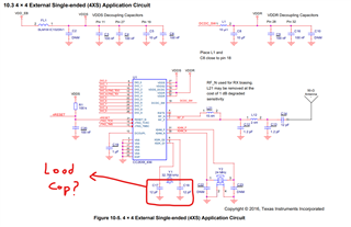
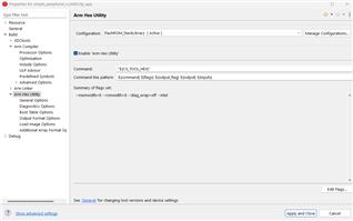
I created a project zero from resource explorer then followed what Markel Robregado answered on the other similar questions. I added the necessary files to Startup folder, adjusted include options etc. But only thing that I am not sure on is configuring the RF Front-End for Custom Hardware section. Actually, I have not understand what I need to change on that section. Could you please explain that section more clear ?

I flashed my code into my custom board succesfully. When I open the Simplelink Connect application on my mobile phone, project zero R2 is shown but when I try to connect, it tries to connect for 3-5 seconds and peripheral connection timeout error is shown. In short my mobile phone see the board but cannot get signal back. Signal power is around -75 and -90 dB. I am not sure whether it is caused from configuring the RF Front-End for Custom Hardware section or my PCB design. I attached the screenshot of the error message on my mobile phone.

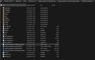
I also attached the some screenshot what I changed.

I am using sdk_5.30 and CCS 12.3.0

Regards,

  • In addition, I tried that with project zero without added any code and simple peripheral code have some configuration but in both same result. 

  • Hi Riza,

    Is your RF Frontend Configuration same with the Launchpad? Then set this define CC2650EM_7ID at CC2640R2_LAUNCHXL.h.

    Anyway, I suggest your design be reviewed by TI Engineer. Just for TI Engineer to reply.

    -kel

  • Hi Kel,

    No, I used single ended RF configuration on my PCB like in the screenshot that I attached. So I defined CC26402EM_CXS in CC2640R2DK_CXS.h file in Startup folder.

    By the way, I thought you are TI engineer. Because you helped me a lot on previous question.

    I can share my design document with TI engineer if it is okay.

    Regards,

  • Hi Riza,

    I am just a forum member here. You seem to be doing everything right. The only thing I notice is you used board files from the folder \\\boards\CC2640R2DK_CXS.

    For example this RF Front End define CC2650EM-4XS also refers to this reference design CC2650EM-4XS-RD. So, normally people would use board files from \\\boards\CC2640R2DK_4XS.

    In your case there is no reference design for CC2640R2DK_CXS.

    I have worked with CC2640R2F 4x4, 5x5, and 7x7mm packages. The board files I use for those custom boards are from \\boards\CC2640R2_LAUNCHXL. The reason is its the most updated. I just modify the board files to work for the custom board.

    The other board files from folders like \\\boards\CC2640R2DK_4XS has not been updated for a long time.

    So, in your case I suggest you use board files from \\boards\CC2640R2_LAUNCHXL.

    Regarding your custom PCB board. The HW team that I worked before in the past starts with a reference design like CC2650 uTag. Then we modify this reference design to our requirements. So, when we have the custom PCB design done there is high chance it will work.

    -kel

  • Hi, Thank you for your suggestion but unfortunately changing the custom board is costly solution because we already had PCBs and I am not sure it is arised from PCB. If TI's hardware engineers review PCB layout, it will be great. But sharing project documents in private would be better.

    In addition, The problem is mentioned in the PCB design consideration document ( https://www.ti.com/lit/an/swra640g)  that I attached seems same that I have. As it says, two capacitors that connected between 32kHz crystal and GND don't exist on my custom board. So this time, I changed the configuration to using 32-Khz Crystal-Less Mode. But except signals dB level, nothing changes, still peripheral connection timeout error.

    By the way, this time the project that I work on is simple_peripheral project. Before 32kHz Crystal Less mode signal dB level is around -50/-70 dB, after using 32Khz Crystal Less Mode signal level becomes weaker ( around -70/-90 dB).

    I also attached the zip and rar file that contains simple_peripheral project. I would appreciate if you control the files for the creating custom board files steps.

    By the way, purpose of the project is reading one of the ADC pin value and sending it to mobile phone. CurrentLP file in the project explorer is imported from Sensor Controller Studio. It is for the make two GPIO pin high. It works exactly on the CC2640R2 LaunchPad. There is no problem on that side.

    Regards,

    simple_peripheral_cc2640r2lp_app_CXS.rar

  • Hi Riza,

    If you would like your design be reviewed by TI Engineer you can submit it through here. https://www.ti.com/tool/SIMPLELINK-2-4GHZ-DESIGN-REVIEWS

    two capacitors that connected between 32kHz crystal and GND don't exist on my custom board

    But, it seems you already know the problem. Also, it is also wise to use the same crystal from reference designs like the launchpad. If you set the program correctly to function 32-Khz Crystal-less mode and you still have a connection timeout it is either your HW has problem or your RF Front End configuration define is not being recognized. Because, if you set that wrong you will have connection problems. Anyway, I will look into your attached file.

    -kel

  • Hi Riza,

    I will give you set of instructions. The objective is just to connect your custom board with your smartphone IOS LightBlue App or Android nRF Connect App.

    1. Create a new CCSv12.3 workspace and import simple peripheral from blestack folder. Rebuild all stack then app.

    2. At Startup folder delete board.c. Then drag and drop board files from C:\ti\simplelink_cc2640r2_sdk_5_30_00_03\source\ti\blestack\boards\CC2640R2_LAUNCHXL. Your Startup folder should look like this.

    3. Open CC240R2_LAUNCHXL.c and go to CC2640R2_LAUNCHXL_initGeneral(). Comment out Board_initHook().

    4. Comment out all entries at BoardGpioInitTable[].

    5. Your RF Front End Configuration is Single Ended External Bias according to this document that does not exist anymore.

    6. Open CC2640R2_LAUNCHXL.h and set RF Front End Configuration define to CC2650EM_4XS

    7. Go to simple peripheral app project properties->Build->Arm Compiler->Predefined Symbols, then set predefined symbol USE_RCOSC.

    8. At simple peripheral app Application folder right click rcosc_calibration.c and unselect Exclude from Build.

    9. At simple peripheral app Startup folder right click ccfg_app_ble.c and select Exclude from build.

    10. At simple peripheral app Startup folder right click ccfg_app_ble_rcosc.c and unselect Exclude from Build. After steps 8, 9 and 10 simple peripheral app folder and files should look like this.

    11. Open simple_peripheral.c Change board.h to Board.h. Comment out include board_key.h.

    12. Enable hex generation utility. Rebuild all then flash the hex file to your custom board.

    Then let me know if you still have connection problems.

    -kel

  • Hi Kel,

    I applied your suggestion to newly imported simple peripheral project step by step then it worked !!! I can connect to mobile phone. So problem does not seem on the HW. Thank you so much.

    But this time I applied the same steps to my modified simple_peripheral project. Unfortunately, it does not shown on the SimpleLink Connect application on mobile phone.  As I mentioned before it is for the ADC value reading. In previous question, you helped me to do it. It might you to remember. To summarize, This is very similar to that link. I created simple_peripheral project. I added the ADC reading codes and some codes from the Sensor Controller Studio to make 2 GPIO pin high into to SimplePeripheral_performPeriodicTask. Because I want to do these things in periodic. Also, I added services to send the data. This program works on the LaunchPad very well without any problem.

     In the attached screenshot, ADC_open function is written with Board_ADC0. It is for the Launchpad. But in my custom board ( it is CC2640R2 DSBGA), I want to assign DIO_11 as a ADC. In creating custom board files, it says that I need to modify but does not say how. Board.h file for the Launchpad. I think the problem arised from that modification problem because I added breakpoint on the ADC_open line then it stops there.

    I hope I could tell my problem. 

    Regards,

    simple_peripheral_cc2640r2lp_app_BGA_not_connect.zip

  • Hi, There are some updates. I changed the files in the Startup directory. I deleted Board.h, CC2640R2_LAUNCHXL.c, CC2640R2_LAUNCHXL.h. ,instead of these files I copied and pastedBoard.h, CC2640R2DK_CXS.c and CC2640R2DK_CXS.c from C:/ti/simplelink_cc2640r2_sdk_5_30_00_03/source_ti_blestack_boards_CC2640R2DK_CXS . This time I could  connect and the features from Sensor Controller Studio works periodically ( make HIGH DIO_7 and DIO_9) no problem about them. Only problem left is how to configure the Board_ADC0 to be DIO_11. I can read the ADC value on my mobile phone and expressions sections on CCS. But they seems like floating value not on the DIO_11.

    Regards,

  • Hi Riza,

    Open CC2640R2DK_CXS.c and go to adcCC26xxHWAttrs[]. Set CC2640R2DK_CXS_DIO11_ANALOG to .adcDIO, see below.

    const ADCCC26XX_HWAttrs adcCC26xxHWAttrs[CC2640R2DK_CXS_ADCCOUNT] = {
       {
            .adcDIO              = CC2640R2DK_CXS_DIO11_ANALOG,
            .adcCompBInput       = ADC_COMPB_IN_AUXIO7,
            .refSource           = ADCCC26XX_FIXED_REFERENCE,
            .samplingDuration    = ADCCC26XX_SAMPLING_DURATION_2P7_US,
            .inputScalingEnabled = true,
            .triggerSource       = ADCCC26XX_TRIGGER_MANUAL,
            .returnAdjustedVal   = 0
        },

    At Board.h

    #define Board_ADC0              CC2640R2DK_CXS_ADC1

    Let me know if this works.

    -kel

  • Hi Kel,

    Finally it works. I connect 3.3V and GND respectively and can see their values on mobile phones. Thank you so much. You helped me a lot.

    Only thing that I change is adcCompBInput. Because CC2640R2DK_CXS_DIO11_ANALOG is defined with ADC_COMPB_IN_AUXIO3 instead of ADC_COMPB_IN_AUXIO7.

    Regards,

  •  Hi ,

    I noticed that after these steps, Simple_peripheral project cannot be connected from mobile phone when I terminate the debug session. 

    I could not find the code lines that caused mentioned problem. Previously, even if I terminate the debug sessions or turn of the power, When I connect 3.3V and GND I could connect the program.

    In addition, I enabled the 'Arm Hex Utility' from the Project > Properties > Arm Hex Utiliy as attached screenshot. Build all and the file is created as attached screenshot. I downloaded UniFlash program. I added the generated hex file into Uniflash and load image and verify image respectively. In the console, It says program load successfully but nothing advertise on SimpleLink application.

    So, If possible I prefer the flash the program by using only CCS.

    Regards,

  • Hi Riza,

    If you have used the board files from C:\ti\simplelink_cc2640r2_sdk_5_30_00_03\source\ti\blestack\boards\CC2640R2_LAUNCHXL with the modification I suggested, it will advertise and connect after flashing the hex file.

    The boards files from C:\ti\simplelink_cc2640r2_sdk_5_30_00_03\source\ti\blestack\boards\CC2640R2DK_CXS I am not sure that this is compatible with simple peripheral from SDKv5.30.

    If your board does not advertise and connect, possible that there is a hang and you need to debug it.

    -kel

  • Hi,

    I used C:\ti\simplelink_cc2640r2_sdk_5_30_00_03\source\ti\blestack\boards\CC2640R2DK_CXS  because my custom board works only with these board files. With board files from C:\ti\simplelink_cc2640r2_sdk_5_30_00_03\source\ti\blestack\boards\CC2640R2_LAUNCHXL here, It becomes non connectable. So, I have to use CXS board files.

    Actually, When I debug and press the resume button, it advertise and become connectable so it works without any problem. The problem starts when I terminate the program. Connection is lost and become not advertising.

    With previous codes (without custom board modification) even if I reset or terminate, while 3.3V is connected, it is advertising but not connectable. This problem becomes after the modification that you suggested.

    Moreover, on the launchpad ( with 7*7 IC) and  C:\ti\simplelink_cc2640r2_sdk_5_30_00_03\source\ti\blestack\boards\CC2640R2_LAUNCHXL board files) , I could connect from mobile phone once it is debugged and no connection lost after termination or reset.

    What I need to  change in the codes to solve this problem? or why program cannot be flashed even if it says "program load succesfully" on the Uniflash.

    I attached rar file that contain all project files.

    Regards,

    simple_peripheral_resume_problem.rar  

  • I used C:\ti\simplelink_cc2640r2_sdk_5_30_00_03\source\ti\blestack\boards\CC2640R2DK_CXS  because my custom board works only with these board files. With board files from C:\ti\simplelink_cc2640r2_sdk_5_30_00_03\source\ti\blestack\boards\CC2640R2_LAUNCHXL here, It becomes non connectable. So, I have to use CXS board files.

    Just to remind you that you replied 10 days ago "I applied your suggestion to newly imported simple peripheral project step by step then it worked !!! I can connect to mobile phone. So problem does not seem on the HW. Thank you so much."

    If you just copy the original board files from C:\ti\simplelink_cc2640r2_sdk_5_30_00_03\source\ti\blestack\boards\CC2640R2_LAUNCHXL without proper modifications as I have instructed it will hang and not advertise.

    The board files from C:\ti\simplelink_cc2640r2_sdk_5_30_00_03\source\ti\blestack\boards\CC2640R2_LAUNCHXL will work for any CC2640R2F package size as long as you properly modify them.

    Try code diff the board files CC2640R2_LAUNCHXL and CC2640R2DK_CXS and understand the differences.

    What I need to  change in the codes to solve this problem? or why program cannot be flashed even if it says "program load succesfully" on the Uniflash.

    Try SmartRF Flash Programmer 2. Your board needs to work after flashing hex file. If not there is some other problem.

    -kel

  • Hi,

    Firstly thanks your patience. Replying takes plenty of  time because I don't want to give answer without dealing by myself.

    Sorry for the bad explanation, I mean If I apply the instruction you suggested ( the board files from C:\ti\simplelink_cc2640r2_sdk_5_30_00_03\source\ti\blestack\boards\CC2640R2_LAUNCHXL and on the freshly created simple peripheral project ), I can connect mobile phone but without ADC related codes. By using C:\ti\simplelink_cc2640r2_sdk_5_30_00_03\source\ti\blestack\boards\CC2640R2_LAUNCHXL files, program becomes only for the connection with mobile phone as you said.

    Adding ADC related codes makes it non advertising and non connectable.  To solve this I use board files from C:\ti\simplelink_cc2640r2_sdk_5_30_00_03\source\ti\blestack\boards\CC2640R2DK_CXS. But this time I can connect and read ADC value only when it is debugging. I went with this way because modifiying board files properly for LAUNCHXL is really hard deal for beginner person.

    After detailed examination, I think flash problem arised from CC2640R2_LAUNCHXL_fxns.c file from C:\ti\simplelink_cc2640r2_sdk_5_30_00_03\source\ti\blestack\boards\CC2640R2_LAUNCHXL. There are flash related codes in that. I copied it from C:\ti\simplelink_cc2640r2_sdk_5_30_00_03\source\ti\blestack\boards\CC2640R2_LAUNCHXL to Startup folder because there is no it's equivalent (do the same job file) in C:\ti\simplelink_cc2640r2_sdk_5_30_00_03\source\ti\blestack\boards\CC2640R2DK_CXS. I think I need to make some modification CC2640R2_LAUNCHXL_fxns.c file for making it suitable work with CXS package IC but I could not. Because functions defined on the board files from C:\ti\simplelink_cc2640r2_sdk_5_30_00_03\source\ti\blestack\boards\CC2640R2_LAUNCHXL. Also SPI  pin numbers are not same for the CXS package. Is there a flash related file (do the same job) for the CXS package ? or how can i make modification on it ?

    Also, I tried to flash by using SmartRF Flash Programmer 2. It also show success like Uniflash but nothing changes on mobil 
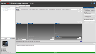
e phone ( no advertisement). I attached the screenshot. I connected 3V3, GND, RESET, TMS and TCK as always from the Launchpad. Is there any other device needed or just Launchpad is enough for to flash from SmartRF Flash Programmer 2.

    Regards, 

  • Hi Riza,

    At CC2640R2DK_CXS.c -> BoardGpioInitTable[], comment out all the table entries. 

    -kel

  • Hi, already commented out as you suggested. Tried as a uncommented, commented except PIN_TERMINATE, all commented.

    All commented doesn't work. Commented except PIN_TERMINATE doesn't flash. Uncommented doesn't flash.

    Here are the 3 version.

     *  =============================== PIN ===============================
     */
    #include <ti/drivers/PIN.h>
    #include <ti/drivers/pin/PINCC26XX.h>
    // commented by riza 6.11.23
    const PIN_Config BoardGpioInitTable[] = {
    
    //    CC2640R2DK_CXS_PIN_LED3 | PIN_GPIO_OUTPUT_EN | PIN_GPIO_LOW | PIN_PUSHPULL | PIN_DRVSTR_MAX,  /* LED initially off */
    //    CC2640R2DK_CXS_PIN_LED4 | PIN_GPIO_OUTPUT_EN | PIN_GPIO_LOW | PIN_PUSHPULL | PIN_DRVSTR_MAX,  /* LED initially off */
    //    CC2640R2DK_CXS_KEY_SELECT | PIN_INPUT_EN | PIN_PULLUP | PIN_HYSTERESIS,                   /* Button is active low */
    //    CC2640R2DK_CXS_KEY_UP | PIN_INPUT_EN | PIN_PULLUP | PIN_HYSTERESIS,                       /* Button is active low */
    //    CC2640R2DK_CXS_KEY_DOWN | PIN_INPUT_EN | PIN_PULLUP | PIN_HYSTERESIS,                     /* Button is active low */
    //    CC2640R2DK_CXS_KEY_LEFT | PIN_INPUT_EN | PIN_PULLUP | PIN_HYSTERESIS,                     /* Button is active low */
    //    CC2640R2DK_CXS_KEY_RIGHT | PIN_INPUT_EN | PIN_PULLUP | PIN_HYSTERESIS,                    /* Button is active low */
    //    CC2640R2DK_CXS_3V3_EN | PIN_GPIO_OUTPUT_EN | PIN_GPIO_LOW | PIN_PUSHPULL,                 /* 3V3 domain off initially */
    //    CC2640R2DK_CXS_UART_TX | PIN_GPIO_OUTPUT_EN | PIN_GPIO_HIGH | PIN_PUSHPULL,               /* UART TX pin at inactive level */
    
        PIN_TERMINATE
    };
     *  =============================== PIN ===============================
     */
    #include <ti/drivers/PIN.h>
    #include <ti/drivers/pin/PINCC26XX.h>
    // commented by riza 6.11.23
    const PIN_Config BoardGpioInitTable[] = {
    
        CC2640R2DK_CXS_PIN_LED3 | PIN_GPIO_OUTPUT_EN | PIN_GPIO_LOW | PIN_PUSHPULL | PIN_DRVSTR_MAX,  /* LED initially off */
        CC2640R2DK_CXS_PIN_LED4 | PIN_GPIO_OUTPUT_EN | PIN_GPIO_LOW | PIN_PUSHPULL | PIN_DRVSTR_MAX,  /* LED initially off */
        CC2640R2DK_CXS_KEY_SELECT | PIN_INPUT_EN | PIN_PULLUP | PIN_HYSTERESIS,                   /* Button is active low */
        CC2640R2DK_CXS_KEY_UP | PIN_INPUT_EN | PIN_PULLUP | PIN_HYSTERESIS,                       /* Button is active low */
        CC2640R2DK_CXS_KEY_DOWN | PIN_INPUT_EN | PIN_PULLUP | PIN_HYSTERESIS,                     /* Button is active low */
        CC2640R2DK_CXS_KEY_LEFT | PIN_INPUT_EN | PIN_PULLUP | PIN_HYSTERESIS,                     /* Button is active low */
        CC2640R2DK_CXS_KEY_RIGHT | PIN_INPUT_EN | PIN_PULLUP | PIN_HYSTERESIS,                    /* Button is active low */
        CC2640R2DK_CXS_3V3_EN | PIN_GPIO_OUTPUT_EN | PIN_GPIO_LOW | PIN_PUSHPULL,                 /* 3V3 domain off initially */
        CC2640R2DK_CXS_UART_TX | PIN_GPIO_OUTPUT_EN | PIN_GPIO_HIGH | PIN_PUSHPULL,               /* UART TX pin at inactive level */
    
        PIN_TERMINATE
    };
    

  • Hi Riza,

    Set up your code to use the CC2640R2_LAUNCHXL board files as I have instructed. Flash the hex file and test it that it is able to connect to smart phone. This is important. If the board does not advertise after flashing hex file, then there is some other problem.

    So basically the ADC codes from CC2640R2DK_CXS.c  you need to port to CC2640R2_LAUNCHXL.c.

    All the pin defines at CC2640R2_LAUNCHXL.h like CC2640R2_LAUNCHXL_DIO0 you need to set as PIN_UNASSIGNED.

    It's not difficult, but you need to be precise when you do this.

    -kel