This thread has been locked.

If you have a related question, please click the "Ask a related question" button in the top right corner. The newly created question will be automatically linked to this question.

ISO35 differential output voltage magnitude > Vcc

Other Parts Discussed in Thread: ISO35

The ISO35 device has proven to be a solid part for our isolated RS422 ports, and proven well over long distances and isolation testing.

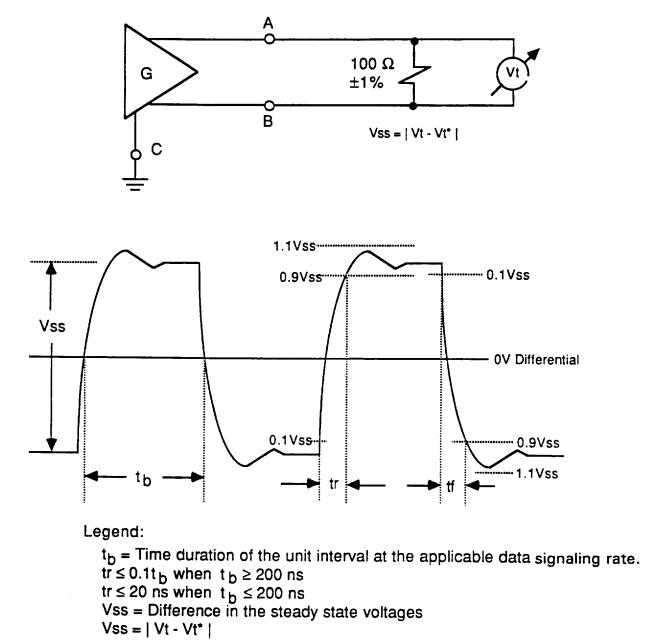
One item we have noticed is, while the datasheet specifies the Differential output voltage (Vod) magnitude as Vcc max, for Vcc = 3.6V we have measured the Vod at low load at approximately 4.5V (Vcc + 0.9V).

While this Vod is well within RS422 spec of < 10V, is the 4.5V Vod of concern with the part, or may this be expected under low load conditions?

Thanks,

Greg

  • no, the absolute bus voltage at each bus pin is specified with -7 to +12V. The actual Vid can vary between -12 to +12V.

    Cheers, Thomas

  • Hi Thomas:

    Thanks for the reply, however my question is not in regards to the input voltage differential that may be applied to the receive pair (Vid) but rather the differential output voltage (Vod) that the ISO35 full-duplex transceiver is sourcing on the transmit pair.

    Our application uses the ISO35 in full duplex mode (separate differential pairs for tx and rx, or 4-wire mode.) My test configuration is shown below, per the RS422 electrical spec, where the transmit differential pair TX+ (A) and TX- (B) are loaded with 100 ohms. The differential output voltage Vod (Vss) is measured across the load resistor. For this test I am running a very short (< 6 inch) twisted pair cable between the ISO35 device TX pair and the 100 ohm load resistor.

    Per the ISO35 datasheet, the maximum Vod (or Vss) I should measure is the VCC applied to the ISO35 device, or 3.6V in our application.  However, as shown in the plot below, the differential output voltage measured is approx. 4.5V (or VCC + 0.9V). I rounded to 4.5V to account for any error in my single-ended measurements, using the CH1-CH2 math function on the oscope.

    If you would, can you please confirm that the measured ISO35 TX differential output voltage (Vod) measured across a 100 ohm load with a short (< 6in) cable may be greater than the value spec'ed in the ISO35 datasheet (VCC), or does this measured discrepancy with the datasheet point to a problem with the device?

    Thanks,

    Greg

  • Hi Greg,

    It looks like you're using a Math function to compute the differential bus voltage. Are you using 'Magnitude' for each of the lines? It seems that you're seeing about double of what the differential voltage should be, and I'm thinking it may be a calculation error on the 'scope. 

    Let us know what formula you are using.

    Thanks,
    Jason Blackman 

  • I see your scope picture is correct, but you might have misinterpreted it. A simple way to find out what the math function tells you is, doing the single-ended measurements on the left. There you see the difference between Va (measured against ground) and Vb (measured against ground) is 2.3V in magnitude (which the data sheet specifies as typical value.

    The math-function however, measures Va against Vb, so the actual Vid. Here in one cycle you have Va being 2.3V more positive than Vb, in the opposite cycle Va is 2.3V more negative than Vb. You therefore get a signal swing around  0V Vid.

    Hope this helps. Thomas


  • Hi Jason, Thomas:

    Thank you for the replies, and I believe I see the difference now lies between how the RS422 electrical spec specifies "Vss" and the ISO35 datasheet specifies "Vod."

    The RS422 electrical spec defines Vss as the difference in steady state voltages across a 100 ohm load resistor that is connected between TX+ ("A") and TX- ("B"). The steady state values are defined as Vt and Vt*, corresponding to the positive steady state voltage (A > B) and the negative steady state voltage (A < B). By measuring at points A and B and plotting A-B I obtained the Vss plot provided previously. The plot on the right that Thomas provided above is a Vss measurement: it shows the differences between the two steady state differential voltages.

    The ISO35 datasheet specifies the differential output voltage magnitude ( | Vod | ) as the absolute value of the voltage difference across TX+ and TX- outputs for various values of load resistance. This value responds to the rectified steady state differential voltages that may be seen, and only provides one component of the Vss measurement: the absolute value of either Vt or Vt*.

    To calculate the expected RS422 difference in steady state voltages across a 100 ohm resistor (Vss) from the ISO35 datasheet, the differential output voltage magnitude | Vod | at RL = 100 ohms may be used:  Vss = 2* | Vod |= 4.6V max.

    With this understanding, the data I measured matches the ISO35 datasheet and meets the RS422 electrical specifications.

    Thanks,
    Greg 

  • how can 0.9vss and 0.1vss be at same level in the waveform.