Hi Wolfgang,
BTW is there a limit to the switching frequency above which internal or external compensation should be selected?
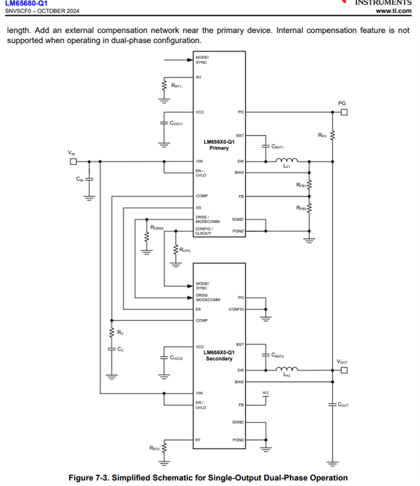
There is no limit but external compensation allows the user to have greater flexibility in adjusting the loop bandwidth and phase margin.
Another question regarding the datasheet of the LM65680-Q1.Table 7-4 shows that connecting the DRSS/MODECOMM pin to VCC or leaving the pin unconnected leads both to the same behavior of DRSS and the Slew Rate Control.
However, ‘Short to VCC’ contains a reference to a footnote that does not appear anywhere.
What is meant by the reference (1)?
Thanks for catching that issue. We will fixed the issue once the part is released to full production. The reference refers to: "This configuration is only valid for single-phase operation."
Ben
Part Number: LM65680-Q1
Tool/software:
Hello there,
I have 3 questions
I am trying to use LM65680 for my power supply design with below requirement (which I think it's suitable for my application)
Is there a similar module but output being negative? so
Also, which metric do I use to calculate junction temperature given that I am going to use its exposed thermal pad and this chip will dissipate quite a bit of power? For example, assuming 90% efficiency, it's expected to dissipate 20W across the IC. (30*6/0.9).
Would you please also suggest part that can meet below requirement
I would prefer to have a single spilt supply module that has two output with above requirement, but not sure if there is anything that exists
Thank you
Part Number: LM65680-Q1
Tool/software:
Hi,
I have design one dcdc 15V/8A with the P/LM65680-Q1 IC of TI.
Now we will produce 5 Prototypes with P/LM65680-Q1 samples.
When we can expect that the LM65680-Q1 or P/LM68680-Q1 is available in quantities ( 100x or 500x)
this is for us very important to know because we will produce a serie of 100x in 2025.
Please a feedback, This is important to know if we must use another IC for the dcdc 15V /8A
Thanks
Part Number: LM65680-Q1
Tool/software:
Hi, Team
One of my customer, KyungShin is looking for solution, 48V to 12V@16A(max).
I understand LM65680-Q1 can support up to 8A and has interleaved mode (paralleled outputs) with accurate current sharing for supporting output current up to 16A.
if this part can support up to 12A with interleave mode, what about output voltage? Could this support up to 12V? that is 12V@16A?
Part Number: LM65680-Q1
Tool/software:
Hello everyone and TI teams.
I am currently designing my board's power stage which would ideally allow to convert one 36Vdc line in two separate lines:
- A 24Vdc power supply for the motors and drivers
- A 3.3Vdc line to power all my control and logic ICs (mcu, transceivers etc.).
I was considering using the LM65680 to achieve the 36Vdc to 24Vdc conversion, and using an LM76003 to achieve the drop to 3.3Vdc.
As I want to meet the IEC-61325 standard, which associated EMI standard is CISPR11, I am willing to optimize my board's design to reduce a maximum the risks of EMI event I could have to face.
Knowing that I which of the following configurations do you think would fit my need the best:
- Connecting my two converters in parallel from the same +36Vdc line, using the same switching frequency and synchronizing the to facilitate EMI filtering on the 36Vdc line before both of them. Which from what I understood would also isolate my logic supply from the perturbation induced while driving the motors (feel free to tell me if I am wrong, I'm willing to learn).
Or:
- Connect firstly the LM65680 to the 36Vdc line and drop to 24Vdc line that will supply my motors and drivers, and connect my LM76003 to this same 24Vdc line to achive the drop to 3.3Vdc to allow local filtering for this specific derivation?
Thank you in advance for your time and advices.
PS: I will also consider any alternative design idea if you think it is more optimized.
Part Number: DS90UH948-Q1EVM
Tool/software:
Hello Support,
We have two new FPD-III Link boards one based on DS90UH948-Q1EVM and one based on DS90UH949A-Q1EVM
We are looking for the source code and compiled files for the MSP430F5529IPN that is on each board (U10 on '949A-Q1EVM board, U4 on '948-Q1EVM board).
Additionally, we would appreciate any quick "how to" instructions relating to how to flash the compiled files into the MSP430F5529IPN.
If a boot loader is required for the MSP430F5529IPN, then we would like that compiled code and any instructions for that, too.
Thanks,
- AR
Part Number: LM65680-Q1
Tool/software:
This new circuit meets, in principle, my design requirements. I have simulated it in Webench to see if it can deliver the voltages and currents I need and so far it is OK but I would need to simulate it in PSpice. Please can you generate the simulation file, it would be very helpful.
thank you
Part Number: DS90UH983-Q1EVM
Tool/software:
Dear TI Support Team,
Could you please let me know where can I buy these two development kits?
- DS90UH983-Q1EVM
- DS90UB984-Q1EVM
Thanks and Best Regards,
André Melo
Part Number: DRV8263S-Q1EVM
Hi,
I'm using DRV824x_DRV814x_DRV8x63-Q1EVM-GUI v1.10.1 to test the DRV8263S-Q1EVM.
It let me drive the DRV8263 but I'm facing limitations to tune PWM frequencies and slew rates.
Is is possible to have an update of the µC SW to have:
Thank you in advance for your support,
Benjamin
Part Number: DS90UB954-Q1EVM
I'm integrating DS90UB954-Q1 as RX for a custom drone camera extension with TIDA-050060 UB953 TX. Need EVM schematics/PCB/Gerbers for RX board fab (MIPI CSI-2 output to processor). Thanks!