Part Number: TIDM-02010
Tool/software:
Hi Experts,
We are developing a board inspired by the TIDM_02010_DMPFC design. Currently, we are tuning the PFC’s current loop using the SFRA tool. While analyzing the function DCL_runDF22_C4, which is a C implementation of DCL_runDF22_C1, we observed an issue related to external modification of the variable x1.
If the value of x1 is modified externally (e.g., by the PFC ISR function), it causes the controller's coefficients B1, B2, A1, A2 to lose their relevance. This is because once x1 is altered externally, the internally calculated values of x1 and x2 no longer influence subsequent computations in the controller.


This raises the question: what is the purpose of modifying x1 externally? If the external modification of x1 renders the controller's internal calculations ineffective, it might undermine the intended functionality of the control loop. Understanding the reasoning behind this design choice is critical to ensure the controller behaves as expected and achieves the desired performance.
Regards,
Ankit Saxena
Part Number: TIDM-1000
Tool/software:
Hello,
For debugging purpose, I would like to use DAC that are available on TIDM-1000 PFC evaluation board, on connector J5 :
In PowerSuite SW I think that DAC function is not used, am I right ?
How shall I modify the code to use it ?
Thanks,
Best regards,
Julien
Part Number: TIDM-02010
Tool/software:
Hi,
According to the TIDM-02010 Schematic, the RC values for Vac are as follows:
When using the Sample Time Calculator in SysConfig (with a Settling Error [LSB] of 0.5), it calculates the Sample Window as 335 SYSCLK counts, which is approximately 2790.61 ns.
However, in the code, a Sample Window of 20 is used (#define PFC_V_ADC_SAMPLE_WINDOW 20) for PFC VAC ADC.

I am having difficulty understanding the calculation behind this discrepancy. Could you please explain the reasoning behind this?
Additionally, I would appreciate it if you could help clarify the concept of Settling Error, as it is not entirely clear to me.
Thank you!
Part Number: TIDM-02010
Tool/software:
Hi Experts,
We are using a reference design for our PFC proof-of-concept (POC). However, after removing the EPWM_setPeriodLoadMode function call to enable access from the shadow register, we observed unexpected oscillations in the current waveform. Since we have not modified the actual PWM period, we are trying to understand how this change is affecting the system.
Below is a code snippet from hal.c, specifically the HAL_setupPWMsPFC function, where we made this modification.

Could you provide a detailed explanation of how EPWM_setPeriodLoadMode works and how its removal could lead to oscillations in the current waveform?
Thanks!
Part Number: TIDM-02002
Tool/software:
Hi,
We are currently considering whether it is possible to digitally control a power system consisting of a three-phase AC input followed by PFC and DC/DC conversion.
We are planning to use separate MCUs to independently control the PFC and DC/DC stages:
The PFC stage (from three-phase AC input) will use a totem-pole topology
The DC/DC stage will use a CLLC topology
To begin, we would like to gain a basic understanding of how to implement such control using TI’s C2000.
Could you please recommend any reference designs using TI C2000 that demonstrate three-phase totem-pole PFC control and CLLC DC/DC control?
Thanks,
Conor
Part Number: TIDM-02010
Tool/software:
Hi,
I am seeking documentation that explains the calculation of IacRef, particularly the role of pfcVars.VinvSqr, which is causing some confusion.
Additionally, I would greatly appreciate any documents or resources that explain the calculations in the PFC ISR function (pfcCtrlISR) in detail.
Part Number: TIDM-1000
Tool/software:
Hello,
I started using TIDM1000 PFC Eval Board with Power Suite tooling.
I went through INCR_BUILDS 1 to 4 but I have an issue with current quality.
My set-up is :
Use of power suite with TI software
TIDM board is supplied with up to 230Vrms (phase-neutral) / 50Hz voltage through an autotransformer (we set the voltage between 0Vrms and 230Vrms)
Earth of TIDM board (connector J3, pin 2) is connected to autotransformer earth
Output neutral of autotransformer is connected to DC mid point for builds 1 to 3 as requested by user manual
500 ohms / 1 kW resistor is used as a load
Im using F28377 µC board, configured as shown here :

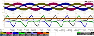
Oscilloscope channels :
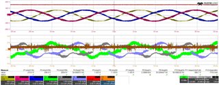
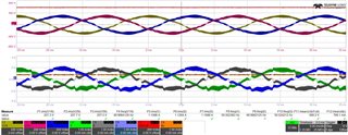
C1, C2 and C3 : input phase-neutral voltages
C4, C5 and C6 : input phase currents
Test results :
INCR_BUILD_1, input voltage = 120Vrms (phase-neutral), VIENNA_dutyPU_DC = 0.5 :
=> input voltages are noisy because our autotransformer is sized for 230Vrms ; I used 120Vrms to be representative of what is done in user manual
=> nevertheless currents are as expected (fig. 25 and 26 of user manual)
=> I consider this build with my set-up to be OK
INCR_BUILD_2, input voltage = 120Vrms (ph-N), VIENNA_iLRef_pu = 0.2 :
=> currents on phases 1 and 3 (C4 and C6) look correct, while phase 2 current is distorded (C5)
=> I checked PWM signals, they all look correct and are similar together, including for phase 2 (I didn't go into details, I just checked general shape)
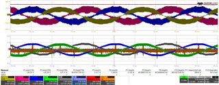
INCR_BUILD_2, input voltage = 230Vrms (ph-N), VIENNA_iLRef_pu = 0.11 :
=> input voltages are cleaner now
=> but phase 2 current is still distorded
=> at this step I tested different Kp value for current regulation, without any improvment ; finally I kept default value Kp = 2
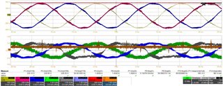
INCR_BUILD_3, input voltage = 208Vrms (ph-N), VIENNA_vBusRef_pu = 1.32 [600V] :
=> not in accordance with figure 56 from user manual
INCR_BUILD_4, neutral disconnected, input voltage = 208Vrms (ph-N), VIENNA_vBusRef_pu = 1.32 [600V] :
=> not in accordance with figure 56 from user manual
Do you have any idea why current are distorded ? What can I check ?
I am working with 50Hz input voltages, is it a problem ?
Thanks,
Best regards,
Julien
Part Number: TIDM-02013
Hi,
There are 2 totem pole topologies.
1. interleave totem pole (used in TIDm-02013)
2. Totem-Pole Bridgeless PFC (Diode Rectification)
My question is can we use Totem-Pole Bridgeless PFC (Diode Rectification) for bidirectional OBC?
Part Number: TIDM-02013
Can the PFC output voltage be changed to 84V through firmware?
I've ordered the product but was unsure regarding if the PFC was according to my application.
The input for my application is (240V) AC and output is (84-90V) DC.
Regards,
Pirdain Bhalla
Hello Venkatesh,
Sorry, for the delay in responding to your question. Currently we have TIDM-02013 (https://www.ti.com/tool/TIDM-02013#design-products), the 7.4kW 1-ph AC OBC reference design. The AC-DC stage of this design is a TTPLPFC. But, the PFC stage is not a full soft switching solution as ZVS is achieved through synchronous rectification.
Thanks
Srikanth