This thread has been locked.

If you have a related question, please click the "Ask a related question" button in the top right corner. The newly created question will be automatically linked to this question.

Class-D Amplifier TPA3111D1PWP driving Ultrasonic Transducer Array.

Other Parts Discussed in Thread: TPA3111D1

Hi,

As part of a Parametric Speaker prototype I am currently working on, I am planning to drive an Ultrasonic Transducers Array using a TI Class-D Amplifier TPA3111D1PWP.

An Array of 50 transducers with the Specifications below[1], arranged in a parallel mode as can be seen in an attached figure.
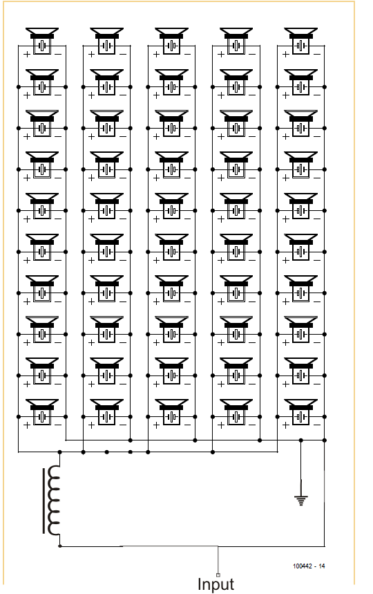
As a result, the Array is to be driven by 10[W] and will present resistance of 20[Ohm] and conductance of 100[nF].

Would be glad to have your advice on the following issues:

  1. Is the TI Class-D Amplifier TPA3111D1PWP suitable to drive such a circuit?
  2. If the array to be connected to OUT+ and OUT-, what are the values of the L1 and L2 to be used?
  3. If the array is to be connected via a Molex connector, what are the values of the FB1 and FB2 to be used?

[1] http://www.mouser.com/ds/2/209/KT-400244-193495.pdf

Thanks in Advance.

    1. Is the TI Class-D Amplifier TPA3111D1PWP suitable to drive such a circuit?

      Peter:  we can use TPA3111D1PWP to drive Ultrasonic Transducer Array, but need change the output LC filter.  The load impedance is 20ohm, so in order to achieve 10W,  PVCC maybe need more than 22V.

    2. If the array to be connected to OUT+ and OUT-, what are the values of the L1 and L2 to be used?

                 Peter: because the load is 20ohm, so need change LC filter's value to get a proper Q and cutoff frequency. LC filter on TPA3111D1's EVM is 22uH+0.68uF, the F0 of this filter is 41.1kHz, Cutoff frequency is 60.8kHz. The F0 is too low for this application.

    Because the Ultrasonic Transducers Array's work frequency is 35kHz~45kHz, so we need make sure the 'Gain vs Input Frequency plot' is flat. I have tested it in Lab, shown as below (You can see the gain variation is 5dB with 22uH+0.68uF):

    change the filter from 22uH+0.68uF to 6.8uH+0.1uF, then test again, data shown as below:

    3. If the array is to be connected via a Molex connector, what are the values of the FB1 and FB2 to be used?

    Do not recommend they use FB, because the PVCC>22V, the EMI maybe a issue with FB in high PVCC value.

  • Hi, Sky
    You can also take below application note for your reference:
    www.ti.com/.../sloa119b.pdf
  • Thank you Peter for the detailed and informative answer.

    Will review and update.

    Regards,

    Simyon.

  • Hi, Sen
    Any update for this? If there is no other questions I will close this thread. Thanks.
  • Thank you Peter.

    No further questions for now.