This thread has been locked.

If you have a related question, please click the "Ask a related question" button in the top right corner. The newly created question will be automatically linked to this question.

AFE 4400 - SPI Communication

Other Parts Discussed in Thread: AFE4400, AFE4490

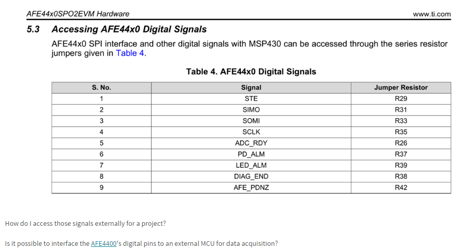
I'm having some issues regarding arduino SPI communication. I removed the 9 resistors as suggested in table 4, but I still couldn't stabilish the communication. I made a quick research and I found that Chip Select should be on. Do you have any suggestions or any other materials to help me ?

There are some other topics that I wanted to discuss with you:

1- I wasn't able to reach success regarding the communication between the AFE board and arduino. I only get "0" as a response. I  also tested the same sittuation with MATLAB, getting the same result.

2- I'm only using 4 pins, from 9 available. (MISO,MOSI,CLOCK,STE). Do I need to use all 9 ? If yes, how?

3- Just for you to know Im connecting all GND pins to one another.

4- How can I send bytes? Is it one by one or all at the same time?

5- For writing data, I'm clearing the SPI-READ bit (0), and for reading data I'm setting SPI-READ bit (1) .

  • Hi Matheus,

    For SPI Write/Read you need 5 signal: STE, SIMO, SOMI, SCLK and AFE_PDNZ. Out of these AFE_PDNZ should be always pulled HIGH and only during the SPI operation STE should be pulled LOW.
    Before you do SPI read lets make sure that SPI write is really happening. You could do this using following procedure.
    1) Apply reset signal to AFE4400: Pull AFE_PDNZ low for sometime and pull it high.
    2) Observe the BG Pin ( C41 in the EVM) : It should be HIGH.
    3) Set PDNAFE bit in CONTROL2 (I.e. 0x23<0> = 1, D0 bit of 0x23)
    4) Observe the BG pin: This time it should ne LOW.

    If SPI write is indeed happening , you can set SPI_READ bit in CONTROL0 and read back the registers. However for the data capture you need ADC_RDY signal as well.

    Regards,
    Prabin

  • Hello Mr. Prabin,

    I followed all the steps given in your answer, but I still couldn't be succesful.
    I'm doing as follows:

    For arduino-AFE conection:

    D8--->AFE-PDNZ (biased high)
    D9--->AFE-STE (biased low)
    D11--->SIMO
    D12--->SOMI
    D13--->SCLK (8MHz)
    GND--->GND
    POWER---> USB(PC)

    Software programming:

    I've reset pin AFE-PDNZ (LOW PULSE ---> DELAY ROUTINE ---> HIGH PULSE), and after this process pin BG didn't go HIGH.
    I've sent all the registers values the same as the ones of GUI.

    The write register routine is as follows: (SPI READ ---> CLEAR)

    void AFE4400Write (uint8_t address, uint32_t data){

    digitalWrite (STE,LOW);
    SPI.transfer (address);
    SPI.transfer ((data >> 16) & 0xFF);
    SPI.transfer ((data >> 8) & 0xFF);
    SPI.transfer (data & 0xFF);
    digitalWrite (STE, HIGH);
    }

    The read register routine is as follows: (SPI READ ---> SET)

    uint32_t AFE4490Read (uint8_t address)
    {
    uint32_t data=0;
    digitalWrite (SPISTE, LOW); // enable device
    SPI.transfer (address); // send address to device
    //SPI.transfer (data);
    data |= (SPI.transfer (0)<<16); // read top 8 bits data
    data |= (SPI.transfer (0)<<8); // read middle 8 bits data
    data |= SPI.transfer (0); // read bottom 8 bits data
    digitalWrite (SPISTE, HIGH); // disable device

    return data; // return with 24 bits of read data
    }

    I've used a scope to test the clock signal, but the signal looked more like a noise signal.

    Please is there any sample code for me to analyse ? or any other kind of help ( can be even a picture of some hardware schematics).

    NOTE: after the removal of the resisters of table, the infra-red led gone off (DB9 cable) .
  • Hi Matheus,

    Could you please confirm the power supplies to AFE4400 as follows?

    RX_ANA_SUP = RX_DIG_SUP = 3V

    TX_CTRL_SUP = LED_DRV_SUP = 3.3V

    In addition to this RESET = AFE_PDN = 3V.

    If all of above voltages are proper, you should get HIGH at BG pin ( while measuring BG make sure you probe the pad going towards AFE4400)

    Regards,

    Prabin

  • Hi, Prabin

    The voltage was checked, as follows:

    RX_ANA_SUP = RX_DIG_SUP = 3.05V

    TX_CTRL_SUP = LED_DRV_SUP = 3.31V

     AFE_PDN = 3.33V

    After reset the pin BG = 1V. this is correct ?

  • Hi Matheus,

    Yes, this is correct but RESET pin should also be pulled HIGH.
    Now you can verify the SPI write by following the following steps.
    1) Apply reset signal to AFE4400: Pull AFE_PDNZ low for sometime and pull it high.
    2) Observe the BG Pin ( C41 in the EVM) : It should be HIGH.
    3) Set PDNAFE bit in CONTROL2 (I.e. 0x23<0> = 1, D0 bit of 0x23)
    4) Observe the BG pin: This time it should be LOW.

    Regards,
    Prabin
  • Hi Prabin, 

    The suggested steps were followed, but the AFE4400 continued to return the value 0.

    The AFE4400 LEDs do not blink when I send some value to set some register or something similar differently from the GUI when it sends all the data packets or when a register is set.

    The only led that lights up is the AFE4400 power supply. As has been said before, the board does not return any value.

    You could show some Arduino SPI communication code with the AFE4400 or show how to set the CONTROL2 value correctly please.

    Matheus,
     
    thank you

  • Hi Matheus,

    Did the SPI write happen(i.e. did BG go LOW when you write 0x020101 to CONTROL2?)?
    LEDs will not blink when you do SPI operation with Arduino. These LED are controlled by MSP430 not by AFE4400. That is why you are seeing only LED for power supply lit up.
    You have to write 0x020100 to CONTROL2 register for normal operation.
    Also can you please observe all the SPI lines during any SPI write operation with and without AFE4400.

    Regards,
    Prabin
  • Hi Prabin, 

    Follow the AFE4400 and AFE4490
    SPO2 Front End Demonstration Kit
    Message Communication Protocol v3.0:

    I have some question:

    Is this message protocol above useful for use with the AFE4400?
     
    If it is a communication protocol with the MSP430 which message protocol should I follow to communicate with the AFE4400?

    Does the MSP430 use any of its own communication protocols with the AFE4400 or does it follow the same protocol mentioned above?

    I would like to know more about communication MSP430 - MCU (Arduino) - AFE4400

    Thank you, Prabin

    Matheus Xavier.

  • Hi Matheus,

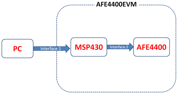
    There are two interfaces in AFE4400EVM as shown in figure below.

    The protocol in your previous mail is for "Interface1"( i.e. between PC and MSP430). Similarly "Interface2" is a standard SPI protocol (see Section 8.5 of AFE4400's datasheet). Firmware of MSP430 is written such that it takes command from PC/GUI using Interface1 and translate them to standard SPI protocol (Interface2) while communicating with AFE4400. So if you don't want MSP430 of the EVM, you can use any MCU/Arduino to communicate with AFE4400 using SPI. In this scenario , you should have your own protocol/interface to talk to your MCU/Arduino, but Interface2( between Arduino and AFE4400) should remain same (i.e. SPI). In fact SPI is the only interface that AFE4400 understands.

    You can look at following references for SPI:

    https://www.arduino.cc/en/Reference/SPI

    https://en.wikipedia.org/wiki/Serial_Peripheral_Interface_Bus

    Hope this clear all your doubts regarding the interfaces of AFE4400EVM.

    Regards,

    Prabin.