This thread has been locked.

If you have a related question, please click the "Ask a related question" button in the top right corner. The newly created question will be automatically linked to this question.

Differences regarding USB on AM3352 and AM3359

Other Parts Discussed in Thread: AM3352, AM3359

I'm having problem getting USB0 host up and running on a custom AM3352 board (running u-boot currently). After measuring signals, reading code and interpreting debug outputs I've come to the conclusion that the USB0 is still running in peripheral mode. I've made sure that the ID pin is grounded and is specifying in the u-boot configuration that it should use host mode, i.e.

#define CONFIG_AM335X_USB0_MODE MUSB_HOST

I'm currently running u-boot 2013.01.01 from the meta-ti layer and have a slightly modified am335x-evm board configuration (more-or-less just specifying the correct pinmux and RAM configuration). I've also removed all traces of configuration of the USB1 port (which is not present on the AM3352) to make sure its configuration doesn't interfere with USB0. Still no luck on getting the USB0 port working.

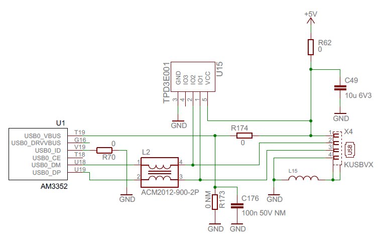
So, I modified the am335x-evm so that it resembles my custom board, i.e. exchanged the micro-usb port for a standard host port and grounded the ID pin. The only difference regarding USB is that the am335x-evm have a USB1 port, and that my custom board has a constant 5V VBUS line. The same u-boot binary boots on both hardware but the USB only works on the am335x-evm.

So, now the question. Are there any differences I should take notice of regarding the USB implementation of the AM3352 (custom board) and the AM3359 (evm board)?

  • The USB peripheral is identical in all AM335X processors. Can you describe how is the USB0_VBUS pin connected on your board?
  • The USB0_VBUS pin is a straight connection between the USB0_VBUS (on the AM3352) and the VBUS pin (pin 1) on the USB port. This connection is then supplied with constant 5V. I do not have the USB0_DRVVBUS output controlling the USB0_VBUS, it's not even connected to anything.

  • This is the reason why Host mode is not functioning properly for you. The USB PHY expects VBUS to be driven by USBx_DRVVBUS after a device connection is detected on the DP/DM lines. I'm not sure if there is a software workaround for this. I will ask someone from the factory team to comment if it's possible to correct this in software.
  • There are many factors which could cause MUSB0 not going into host mode. First please ensure the ID pin is directly grounded or via a resistor no more than 10 Ohms.

    There is also a s/w workaround for not connecting USB0_DRVVBUS pin for VBUS control. Please clear bit19 OTGVDET_EN in USB_CTRL0 register in Control_Module. Please refer to Section 9.3.1.21 in TRM (spruh73i.pdf) for details.

    If all of the above do not help, please post the value of MUSB_POWER and MUSB_DEVCTL registers before and after plugged in the USB device. Both are 8-bit registers.

    Physical Address:

    MUSB0_POWER: 0x47401401

    MUSB0_DEVCTL: 0x47401460

  • It might be going into peripheral mode because it's seeing that constant 5V on the VBUS line.

    I would imagine it's going to depend on exactly what driver you're using. But I had some trouble initially getting USB to work as a USB host. To get it working I had to GND the ID pin. And I drove the VBUS line via a USB power switch which is controlled by the DRVVBUS signal.

    From what I understand (and the TI gurus here can provide a lot more information than I can), if the chip sees 5V on VBUS when it's not enabling the DRVVBUS signal, it thinks, "hey, a PC has been plugged in, I must be a peripheral". If on the other hand it sees VBUS as being 0V when DRVVBUS is not enabled and 5V when DRVVBUS is enabled, then it thinks, "hey, I have control over VBUS, I must be a host". 

    That's been my experience - I hope it helps.

  • Frank,

    You understanding is exactly correct.

    But Setting USB_CTRLx[OTGVDET_EN] to 0 will disable the VBUS voltage sensing. So when DEVCTL[SESSION] bit is set, DRVVBUS will be asserted, and the controller will go into host mode without checking on VBUS voltage. Assuming ID pin is already properly grounded.

    Note this sw workaround should be only used for host-only mode.

  • I've tried setting the USB_CTRL0[OTGVDET_EN] to 0 as discussed and it does help resolving the peripheral/host mode problem. Thanks!

    But it does not work yet, instead it hangs at a completely different step, when the CSR0 register reports error. A debug output from u-boot is attached below (still same binary works on am335x-evm but not on custom board). Is there anything else that I should think of doing on my custom board?

    USB0:   <== regs 47401400 devctl 98
    usbintr (110) epintr(0)
    ** IRQ host usb0010 tx0000 rx0000
    <== Power=f0, DevCtl=5d, int_usb=0x10
    scanning bus 0 for devices... qh 8fa364b8 urb 8ffbc39c dev0 ep0out, hw_ep 0, 8fa2db00/8
    --> hw0 urb 8ffbc39c spd3 dev0 ep0out h_addr00 h_port00 bytes 8
    TX ep0 fifo 47401420 count 8 buf 8fa2db00
    Start TX0 pio
    usbintr (0) epintr(1)
    ** IRQ host usb0000 tx0001 rx0000
    <== csr0 0200, qh 8fa364b8, count 0, urb 8ffbc39c, stage 1
    start IN-DATA
    usbintr (0) epintr(1)
    ** IRQ host usb0000 tx0001 rx0000
    <== csr0 0210, qh 8fa364b8, count 0, urb 8ffbc39c, stage 2
    no response, csr0 0210
    aborting
    complete 8ffbc39c 8fb7b23c (-71), dev0 ep0in, 0/64
    1 USB Device(s) found
           scanning usb for storage devices... 0 Storage Device(s) found
  • Regarding the registers you asked about:

    Before device was inserted

    POWER 0x20
    DEVCTL 0x98

    After device was inserted

    POWER 0x20
    DEVCTL 0x98

    After usb start was run in u-boot (i.e. after initializing and failing to communicate with device).

    POWER 0xf0
    DEVCTL 0x5d
  • The log shows AM335x USB host is unable to receive the requested USB packets from the device, (or maybe the device did not received the USB request so it did not send the requested packets...). It seems like to be a signal integrity issue.

    Have you tried to boot the board into Linux and tested the USB module? Is it possible to provide the USB portion of the schematics for review?

  • Currently I have been focusing on u-boot since it's easier to do minor adjustments on it (e.g. direct adressing of memory and smaller codebase) and because I haven't put the effort just yet on getting the same binary to run on both my own hardware and the evm. But I did apply the minor adjustment with OTGVDET_EN on linux mainline 3.11 just now and got the following output upon boot (with DEBUG flags set). Looks the same as u-boot upon first glance.

    [    2.117427] musb-hdrc musb-hdrc.0.auto: qh cf5995c0 urb cf599640 dev0 ep0out, hw_ep 0, cf524840/8
    [    2.126408] musb-hdrc musb-hdrc.0.auto: --> hw0 urb cf599640 spd3 dev0 ep0out h_addr00 h_port00 bytes 8
    [    2.135909] musb-hdrc musb-hdrc.0.auto: TX ep0 fifo d0896420 count 8 buf cf524840
    [    2.143478] musb-hdrc musb-hdrc.0.auto: Start TX0 pio
    [    2.148646] musb-hdrc musb-hdrc.0.auto: usbintr (0) epintr(1)
    [    2.154463] musb-hdrc musb-hdrc.0.auto: ** IRQ host usb0000 tx0001 rx0000
    [    2.161335] musb-hdrc musb-hdrc.0.auto: <== csr0 0200, qh cf5995c0, count 0, urb cf599640, stage 1
    [    2.170397] musb-hdrc musb-hdrc.0.auto: start IN-DATA
    [    2.195077] musb-hdrc musb-hdrc.0.auto: usbintr (0) epintr(1)
    [    2.200904] musb-hdrc musb-hdrc.0.auto: ** IRQ host usb0000 tx0001 rx0000
    [    2.207778] musb-hdrc musb-hdrc.0.auto: <== csr0 0210, qh cf5995c0, count 0, urb cf599640, stage 2
    [    2.216838] musb-hdrc musb-hdrc.0.auto: no response, csr0 0210
    [    2.222738] musb-hdrc musb-hdrc.0.auto: aborting

    Anyway, I've attached the USB portion of my schematics for you.

  • VBUS requires a minimum 120uF capacitance in Host mode.

    How long are the DP/DM traces? 

    How closely are the DP/DM traces length matched?

    Are the DP/DM pairs correctly impedance controlled in the layout? Single-ended impedance should be controlled to 45 Ohms +/- 10% and differential impedance should be controlled to 90 Ohms +/- 15%.

  • Q1: VBUS requires a minimum 120uF capacitance.

    A1: 100uF

    Q2: How long are the DP/DM traces? 

    A2: DP=163,982mm, DM=162,601mm

    Q3: How closely are the DP/DM traces length matched?

    A3: 7-8mil

    Q4: Are the DP/DM pairs correctly impedance controlled in the layout? Single-ended impedance should be controlled to 45 Ohms +/- 10% and differential impedance should be controlled to 90 Ohms +/- 15%.

    A4: Single ended impedance 50ohm, Pair impedance 100ohm (Difficult to be exact the pair changing layer 2-times)

  • - Please add the required capacitance to VBUS.

    - Do all USB devices fail in this manner?

    - Have you tried full-speed and/or low-speed devices?

    - You may try removing the choke...these will negatively affect signal quality.

    - Have you characterized the signal quality? I'd be interested in looking for coupled noise or reduced amplitude.

  • I'm trying to get one of my hardware colleagues to check the hardware according to your suggestions.

    Meanwhile, I've tried plugging in low-speed devices. These are getting harder and harder to find but I managed to get hold of a low-speed USB keyboard. The output is not the same as with a high-speed device, it actually seems like the signals and data is getting through since the correct vendor and product ids are printed. I'm currently looking into why the usb keyboard is not supported although USB HID is enabled in the kernel, but that's off-topic for this thread.

    Without debug outputs enabled the output is as follows:

    [    9.902599] usb 1-1: new low-speed USB device number 29 using musb-hdrc
    [   10.062957] usb 1-1: device v03f0 p0024 is not supported
    [   10.068424] hub 1-0:1.0: unable to enumerate USB device on port 1

    Full debug output can be found on pastie

  • Update: low-speed USB keyboard and full-speed mass storage device has now been tested and works. The last missing piece was that the OTG whitelist was in use and blocking the devices.

    Anyway, high-speed is still not working.

  • Given that LS and FS devices work, and HS devices do not, poor signal integrity is the likely root cause. It would be best at this point to generate a USB eye diagram to evaluate the signal quality.

    A good primer describing this testing is located here :http://www.tek.com/document/application-note/understanding-and-performing-usb-20-physical-layer-testing. Full test procedures and specifications can be downloaded from the USB-IF directly (http://www.usb.org/developers/tools/).

  • An update on my last statement. Low speed devices works fine, full speed does not fully work.

    Me and my colleague has now measured the signals on low and full speed USB. Since we currently do not have access to equipment to measure high speed, we have been focusing on getting these two lower speeds fully working. I'll post our findings below and hopefully you can help us pinpointing what's wrong.


    At 1.5MBPS DM and DP, the transition is correct since they meet in the middle

    At 12MPS DM and DP, the transition is not correct as they do not meet in the middle.

    The USB spec. is not fulfilled, see a snapshot from the standard below.

  • Did you deskew your scope probes before making this measurement?  To confirm your scope or probes do not have different delays on the two channels being used for this measurement, connect both probes to the same USB signal to confirm there is no skew between the two channels being displayed on the scope.

    How do you know the data captured on the scope was being transmitted by the host rather than the peripheral?

    Regards,
    Paul

  • This is a little bit embarrassing but no, the probes where not deskewed before measuring. We have deskewed them and remeasured the D+/D- channels on low and full speed. This time around the measurements seemed fine.

    We have no way of knowing whether the data seen when measuring is from the host or the peripheral. What we do know on the other hand is that both a keyboard (low speed) and a mouse (full speed), both peripherals which presumably sends more data than they receive, seems to works fine.

    Using a usb flash drive on the other hand does not fully work. It seems that identifying, mounting and reading from it works perfectly fine while writing and umounting it does not. I've logged the communication through the Linux usbmon interface and got the following output after converting to more human-readable form with usbmon-parser. I'm interpreting this as it's the output that's the problem. Any ideas on what else to check?

    BOS  CBW => Sig 43425355 Tag 0000008f DataLen 512 Flags 80 Lun 0 CmdLen 10
         CDB => Read10 00 00 00 02 2e 00 00 01 00 00 00 00 00 00 00
    BIS  Data => 00000000 00000000 00000000 00000000 00000000 00000000 00000000 snip...
    BIS  CSW => Sig 53425355 Tag 0000008f Residue 0 Status Pass

    BOS  CBW => Sig 43425355 Tag 00000090 DataLen 512 Flags 80 Lun 0 CmdLen 10
         CDB => Read10 00 00 00 02 2f 00 00 01 00 00 00 00 00 00 00
    BIS  Data => 00000000 00000000 00000000 00000000 00000000 00000000 00000000 snip...
    BIS  CSW => Sig 53425355 Tag 00000090 Residue 0 Status Pass

    BOS  CBW => Sig 43425355 Tag 00000091 DataLen 512 Flags 00 Lun 0 CmdLen 10
         CDB => Write10 00 00 00 00 20 00 00 01 00 00 00 00 00 00 00
    BOS
    urb error -71 => cf559640 795559914 C Bi:1:002:2 -71 0
  • I'm not sure what could be causing your issue, but I do not expect an issue with AM335x hardware.

    We took an AM335x EVM to an official USBIF workshop, hosted a interoperability test suite for testing with multiple peripheral devices and did not find any interoperability issues.

    Regards,
    Paul

  • I hear you, but let's just iterate back to the original question once more. We have the same binaries (both u-boot and linux kernel) running on both AM335x EVM and our custom board. The signals looks fine on 12Mbit on both, but only the EVM actually works. The USB reports error through the ERROR bits in the TXCSR and RXCSR registers.

    One main difference except the AM3352 and AM3359 is that we have the ZCE package while the EVM has the ZCZ. Are there any differences, or anything we should take into consideration when designing for the ZCE package (software or hardware)?

    If that's not the case, we're leaning towards accepting that we have a faulty AM3352 or faulty soldering of it.

    Thanks for your help,
    Mans

  • I'm personally still suspicious of the fact there's a difference between the EVM and your board, namely, that the EVM has VBUS controlled by DRVVBUS and your board doesn't. I understand you've configured the register bits to work around this, but I suspect that in doing so you're treading in largely uncharted territory.

    My first thought would be to suggest you modify your board to add a USB power switch controlled by DRVVBUS. However I understand that unless you already have the DRVVBUS pin available on a testpoint or something, this is physically impossible to do.

    So my second thought would be to suggest you modify your EVM to disconnect (cut trace or something) the DRVVUS signal and have its USB port constantly provide 5V on VBUS. In other words, make the EVM board hardware look as identical as possible to your own board. And see if the problem then appears on the EVM board.