This thread has been locked.

If you have a related question, please click the "Ask a related question" button in the top right corner. The newly created question will be automatically linked to this question.

AM335X: How to use hardware RNG

Hi,

I tried to use Hardware RNG on my non-OS AM335x (non-OS programming reference: http://processors.wiki.ti.com/index.php/AM335X_StarterWare_Booting_And_Flashing)

I only found the setting about TRNG on AM335x with OS at http://processors.wiki.ti.com/index.php/Cryptography_Users_Guide

How can I set Hardware RNG in my C code? (toolchan:IAR)

Thanks!!

  • Hi,

    Please confirm what software you are using. Is it StarterWare (bare bone C) or is it Linux OS. Which version?

    Best regards,
    Miroslav

  • The short summary:

    struct rng {
    /*00*/	u64 output;	//r-
    /*08*/	u32 irq_stat;	//r-
    /*0c*/	u32 irq_en;	//rw
    /*10*/	u32 irq_clr;	//-c
    /*14*/	u32 control;	//rw
    /*18*/	u32 config;	//rw
    };
    
    void rng_init( volatile struct rng *rng ) {
    	rng->config = 34 << 16 | 33;
    	rng->control = 33 << 16 | 1 << 10;
    }
    
    u64 rng_read( volatile struct rng *rng ) {
    	do {} while( (rng->irq_stat & 1) == 0 );
    	u64 output = rng->output;
    	rng->irq_clr = 1;
    	return output;
    }

    The magic tuning parameters are those used by the am335x and ti81xx linux drivers for the RNG.  The rate at which the RNG can produce output is apparently high enough that using a proper IRQ instead of busy-waiting is said to be not worth it.  Clearing the irq bit is required to get a new output value.

    Finally, the relevant addresses for the AM335x which the TRM is kind enough to omit:

    #define CM_PER_RNG_CLKCTRL 0x44e00090
    #define RNG_BASE 0x48310000

    Addendum: although those values are used by the kernel I very much doubt they are correct. For one, it looks like whoever configured those values didn't take into account that min-refill is expressed in different units than max-refill and startup, and using a sample divider of 1 is almost certainly wrong. See first post on next page for more info.

  • Sorry for the delay in responding to your reply.

    I am using StarterWare.

    And I want to generate the True Random Number for my program.

    Best regards,

    Tang

  • For StarterWare questions, please turn to the StarterWare forum.

    Best regards,
    Miroslav

  • I'm pretty sure StarterWare does not include any support for it, so you will need to write the driver for it yourself. If you are interested, I can provide more details on the peripheral (I've learned quite a bit about it since my previous post).

  • Thanks for your replies, I will post my question at  StarterWare forum

    To Matthijs van Duin: 

    Thank you very much. I appreciate your assistance. 

    Can we discuss more detail on my post at StarterWare forum?

    http://e2e.ti.com/support/embedded/starterware/f/790/t/363438.aspx


    Best regards,

    Tang

  • As I mentioned, as far as I know StarterWare has no support for it, so this forum is a more appropriate place to discuss the peripheral I believe.

    The TRNG is a reasonably simple peripheral.  It consists of a SafeXcel EIP-75a random number generator core with a TI-specific wrapper around it.  I already gave an ultra-simplified register map for it earlier.  I've also made a more detailed register map.

    The simplest usage consists of enabling the module via PRCM (CLKCTRL register at 0x44e00090) and then using the example code I gave earlier, which is not optimal but should already suffice to get the RNG functional.  For interrupt-driven usage just set the irq-enable bits, the irq will arrive on line 111 of the Cortex-A8 interrupt controller.

    Please confirm whether you can get the RNG operational with this info or need more details on any of the steps. When I have a bit more time I will post some further explanation on the various config parameters, and how to operate the quality-monitoring/alarm mechanism of the RNG.

  • Thank you very much.

    I have tried the code you proposed before, but the "rng->irq_stat & 1" always be 0.

    In order to that "rng->irq_stat" can get the value, any initialization I have to do?

    Best regards,

    Tang

  • Enabling the module clock and calling rng_init is the minimal initialization strictly needed, and for me this suffices to get output.

    Attached example works for me (tested on beaglebone black): 3823.rng-test.zip

    (in case you're wondering: there's no good reason for the main source file to be C++ here, but I use C++ for all my sources and I was too lazy to fix the Makefile to include the appropriate compiler options for plain C sources)

  • Thank you very much!!

    I can get the random number with your information.

    Best regards,

    Tang

  • Matthijs van Duin said:
    When I have a bit more time I will post some further explanation on the various config parameters, and how to operate the quality-monitoring/alarm mechanism of the RNG.

    As promised, a bit more info:

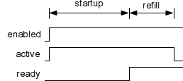
    The RNG apparently consists of 24 free-running oscillators (FROs) as primary source of entropy (randomness).  When the RNG is active, their output is sampled and mixed into an entropy pool.  When enough entropy has been collected, 64 bits are extracted to an output register and the ready-flag (bit 0 of status register) is set.  Since this "consumes" 64 bits of entropy of the pool, sampling continues for a while to refill it after which the RNG shuts down to conserve power:

    Now when software needs random bits, it reads the output register and then clears the ready-flag.  Since the entropy pool is still full, the RNG immediately outputs 64 bits and sets the ready-flag again.  If software immediately reads these too and desires even more bits, it will now have to wait until the RNG has refilled its entropy pool and is ready to output again.  Example showing 4 consecutive reads (256 bits total):

    These timings are determined by four parameters which need to be configured before enabling the RNG:

    • the sample clock divider:  number of cycles (of the module clock) per sample
    • the number of startup samples, to initially fill the entropy pool
    • the minimum number of refill samples to provide the next output
    • the maximum number of refill samples before shutting down to conserve power

    As shown in my register map, the startup and max-refill parameters are 16-bit fields in units of 256 samples, while the min-refill parameter is an 8-bit field in units of 64 samples.  The value zero in all cases encodes the maximum possible: 224 samples for startup and max-refill, and max-refill for min-refill.

    The sample clock divider (range 1-16, encoded as 0-15) is used in case the module clock is higher than useful for sampling the FROs.  The keystone security accelerator user guide offers some guidance on this:

    "This field must be set to a value such that the slowest FRO (even under worst-case conditions) has a cycle time less than twice the sample period."

    The usefulness of this advice is limited by the fact they don't mention any way to determine the cycle times of the FROs, which is probably silicon-dependent.  It is however possible to view the raw samples of a single FRO by the following procedure:

    1. set the max-refill to zero or some large value to make sure the RNG doesn't shut down during the test
    2. set min-refill to 1 (64 samples)
    3. set only a single bit of the "FROs enabled" register to select the FRO you wish to inspect
    4. set bits 1, 2, and 10 of the control register to enable the RNG in test-mode with feedback disabled.
    5. read a batch of values from the RNG

    This gives me this kind of output:

    1011010101011010101101010101101010110101011010101010101001010101
    1010101101010101010101101010101010110101010101111010101010010101
    1010101101010100101010010101011010100101010010101101010110101001
    1101010110101101010010101101010010100101011011001100011100011100
    0001110011100011100011100111000111000111001110011100011000111000
    0011100011100011100011110001111000011110000111110000111100001111
    1110000011111000011111000001111100000111110000011110000111000011
    0011110001111000111100011110001111000011110001111000011110001111
    1111000011110000011111000001111110000001111110000111100011110001
    0001110001111000111000011100011100011110001110001110001110001100
    1100110011001100110011100110011001100111001100110001100110011100
    0111001100111001100111001100100110110010010010011011011011011011
    1001001101101101101100100100110110110110010011011011011001001101
    1100100110011011001100110110011001100100110010011011011011011011
    0010010010010010010010110100101001010110101001010110101011010100

    This is on a dm814x whose security subsystem is clocked at a high rate (200 MHz), and the output above shows this is clearly too high as sampling rate since the FRO period is 10 samples at its slowest while at its fastest it seems about 1-2 samples (the short string of consecutive ones on the second line shows that it briefly approaches 1 sample period).  Setting the sample divider to 6 indeed yields output without any obvious long-range oscillatory patterns.


    To be continued...

    Addendum: since noone seemed interested I didn't bother finishing my discussion of the RNG. If you're reading this and would like futher information on parameter choice or the FRO-failure monitoring and alarm mechanism, feel free to bump this thread.

  • Hi Matthijs van Duin, I am in need of detailed information on the source of entropy (randomness) in the AM335X RNG and noticed you have some insight on it's operation. In particular you mentioned "The RNG apparently consists of 24 free-running oscillators (FROs) as primary source of entropy (randomness)."
    Where can I find more information on this?
  • Multiple sources... The keystone doc I referenced in my last post, as well as the existing drivers (with register names such as RNG_REG_FROENABLE_MASK), the tiny scraps of info you can find on the RNG core used (SafeXcel EIP-75). As I explained in my last post it is also actually possible to see (chunks of) the output of each individual FRO directly, and their output indeed looks exactly like what you'd expect from an FRO (and all 24 seemed to have somewhat different behaviour iirc).