This thread has been locked.

If you have a related question, please click the "Ask a related question" button in the top right corner. The newly created question will be automatically linked to this question.

AM335X eMMC detection on MMC0

Other Parts Discussed in Thread: TMDXEVM3358, AM3358

I'm verifying Beaglebone(A6, white, not BBB) from MMC0 with an eMMC device.
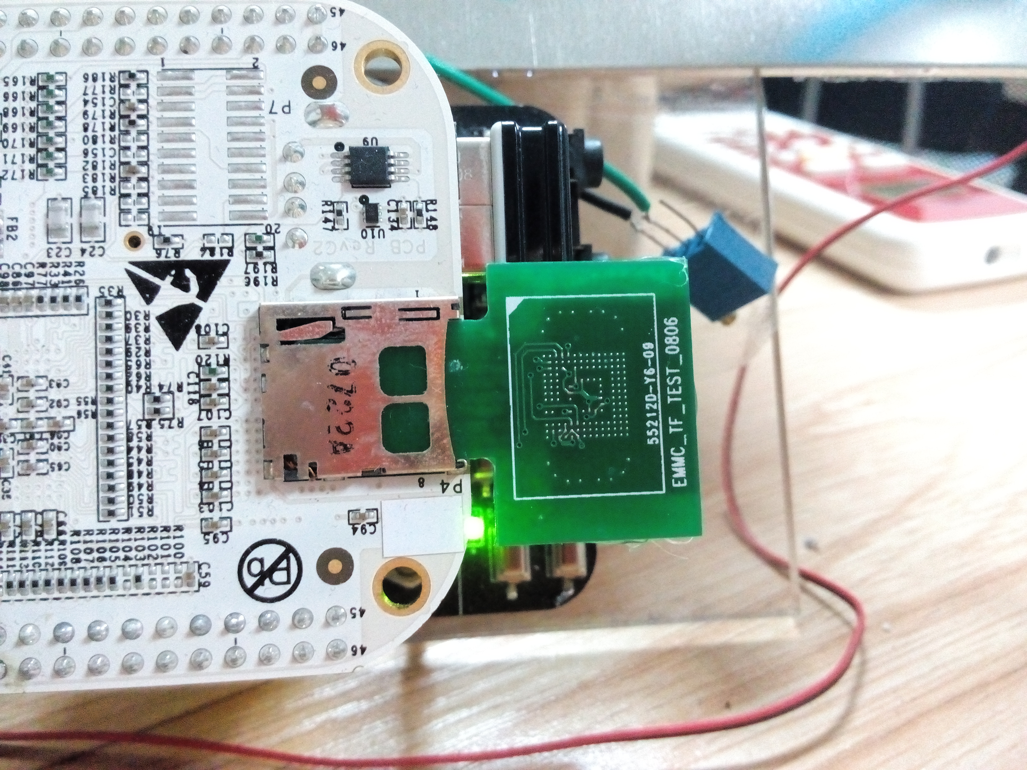
I made an circuit board(driver an 8G eMMC chip) connected to uSD connector on beaglebone, so that it just like a microSD card.(gpio_cd, gpio_wp set to -EINVAL and it's 4 bit mode same as beaglebone uSD)
I can edit content in the eMMC card with an SD Card Reader on PC.

Then I created two partitions on PC, the bootble fat32 partition(ML0,uImage,u-boot.img,env.txt) and the ext3 (rootfs) partition.But Beaglebone can not boot from the eMMC device on MMC0.It just printed "CCCCCC"
I thought somthing wrong then read the AM335X TRM,in Section 26.1.7.53, 26.1.7.55

"The high level flowchart of the eMMC / eSD and MMC/SD booting procedure is depicted in Figure 26-17.
The booting file is searched only in case of booting from a card. eMMC/eSD embedded memories only
support raw mode.
...
As previously mentioned the contents of an MMC/SD card may be formatted as raw binary or within a FAT
filesystem. eMMC / eSD devices only support raw mode. The ROM Code reads out raw sectors from
image or the booting file within the file system and boots from it.
...
The raw mode is detected by reading sectors #0, #256, #512, #768. The content of these sectors is then
verified for presence of a TOC structure as described in Section 26.1.9. In the case of a GP Device, a
Configuration Header (CH) must be located in the first sector followed by a GP header. "

link:http://omappedia.org/wiki/E-MMC_boot eMMC RAW boot
Step-1 : ROM code reads 0th sector from eMMC device.
Step-2 : Check TOC, sets up SDRAM using configuration headers in the TOC.
Step-3 : ROM code reads 1st sector from eMMC device.
Step-4 : Decode the length of the image and load address(SRAM) of the x-loader. And execute it.
Step-5 : X-Loader transfers U-Boot to DRAM and executes it.
Step-6 : U-boot reads Kernel from FAT partition to SDRAM and executes it.
Step-7 : Kernel reads Filesystem.

It seems that I should format the eMMC card in "RAW Mode", but what's the RAW Mode? How make it works as RAW mode ? and what the image file contains?

thx~

  • Hi Yi,

    The important part from the AM335X TRM Rev. K can be found in section 26.1.7.5.2:

    "Each interface has booting restrictions on which type of memory it supports:
    • MMC0 supports booting from the MMC/SD card cage and also supports booting from eMMC/eSD/managed NAND
      memory devices with less than 4GB capacity.
    • MMC1 supports booting from eMMC/eSD/managed NAND memory device with 4GB capacity or greater."
  • It seems that my datasheet is too old(Rev F) , it doesn't contain that section =_=!

    Capacity of my eMMC is 8G. Maybe it's the problem. I will verify it.

    Thanks you very much.

  • What is the reason the MMC0 can only booting from eMMC device with less than 4GB?

    Has anyone successfully tried to boot from the eMMC with 4GB or greater?
  • From MMC1 you can boot with large capacity eMMC. From MMC0 the restriction comes from the processor ROM code - read section 26.1.7.5.2 from the AM335X TRM Rev. L for details.

  • Is there a plan to modify the ROM code for the MMC0 to boot from eMMC with 4GB?
    The reason I am asking is that the MMC1 in my design is being used for GPMC peripheral interface, so that left me with the MMC0 site. Since this design is to be installed on an aircraft, no removable part is allowed. There are eMMC devices from Micron with 2GB, but they don't come with an industrial temperature (minimum requirement for my design).
    From TRM section 26.1.7.5.2, the restriction for the eMMC device was because of the non-compliance of the eMMC v4.41 spec. The Micron website listed their devices do comply with v4.41 spec.
  • Here is my other option to use a 4GB eMMC to boot from MMC1:
    Since we have to have an eMMC device with 4GB or greater to boot from MMC1 site, we have to share it with the GPMC. I have noted in the TRM that "If MMC1 is used the GPMC interface is not usable, due to pin muxing options."
    Is it possible that I use the MMC1 to boot, then after boot up, I change the mode to select GPMC interface?

    What is the output load capacitance of the GPMC?
    Currently, I only have the GPMC tied to an FPGA, I will add an eMMC if switching mode after booting is possible, and I might add a NAND device and/or an MRAM device.
  • Anthony Truong said:
    Is there a plan to modify the ROM code for the MMC0 to boot from eMMC with 4GB?

    No, there are no such plans.

    Anthony Truong said:
    From TRM section 26.1.7.5.2, the restriction for the eMMC device was because of the non-compliance of the eMMC v4.41 spec. The Micron website listed their devices do comply with v4.41 spec.

    Your best bet would be to verify this on an EVM board, as shown on the photo above.

  • Anthony Truong said:
    Is it possible that I use the MMC1 to boot, then after boot up, I change the mode to select GPMC interface?

    I don't recommend this, as there may be glitches on the interface during pinmux switching, which can cause undesired behavior of connected devices,.

    Anthony Truong said:
    What is the output load capacitance of the GPMC?

    This is given in Table 7-20 from the AM335X Datasheet Rev. H.

  • I'm looking into NAND flash option for booting and stumbled upon the evaluation module, TMDXEVM3358.
    It has a daughter card that connects the GPMC bus with the CPLD, which controls the NAND, NOR, and MMC1. Are those devices bootable or only used for general purpose memory interface?

    There is also a NAND device on the motherboard, but it is DNI’ed. Why is it being removed?

    Would there be a loading issue if the NAND is installed because there would be three loads (NAND, CPLD, and LCD) on the GPMC bus?

    -----
    For our design, there would also be three loads, NAND, FPGA, and MRAM, on the GPMC bus.
    Could the system be able to boot with the NAND device with the FPGA and MRAM tied to the GPMC bus?

    Can the NAND Flash be loaded in the initial production phase from the UART / USB interface using the UBoot?

    We have the FPGA interface running at least 60MHz. These three devices will have their own chip select from the AM3358. Would there be issued with loading and/or current source/sink interfacing directly with the CPU?

    If the processor CANNOT handle the three loads, please suggest a buffering topology.
  • Anthony Truong said:
    It has a daughter card that connects the GPMC bus with the CPLD, which controls the NAND, NOR, and MMC1. Are those devices bootable or only used for general purpose memory interface?

    Only the NAND device from these three is used for booting.

    Anthony Truong said:
    There is also a NAND device on the motherboard, but it is DNI’ed. Why is it being removed?

    Because the CPLD allows for different configurations of the GPMC interface. In some of these there will be a conflict if this memory is installed.

    Anthony Truong said:
    For our design, there would also be three loads, NAND, FPGA, and MRAM, on the GPMC bus.
    Could the system be able to boot with the NAND device with the FPGA and MRAM tied to the GPMC bus?

    Yes, if the NAND is connected to the pins shown in Section 26.1.7.4.2.2 of the AM335X TRM Rev. L. Note that there are pins which are not used for NAND boot but are initialized by the ROM code (e.g. GPMC_BE1N, GPMC_CLK). Make sure you read the whole section 26.1.7.4 to select a NAND memory that is supported.

    Anthony Truong said:
    Can the NAND Flash be loaded in the initial production phase from the UART / USB interface using the UBoot?

    Yes.

    Anthony Truong said:
    We have the FPGA interface running at least 60MHz. These three devices will have their own chip select from the AM3358. Would there be issued with loading and/or current source/sink interfacing directly with the CPU?

    This depends on what loads these devices will present to the GPMC bus. See sections 7.7.1 and 5.7 of the AM335X Datasheet Rev. H for specifications.

  • If I don't use for (eMMC on MMC0) booting in that case can I use more than 4GB of eMMC om MMC0?

  • Yes, this is correct. The 4GB restriction is only for booting from eMMC on MMC0.