This thread has been locked.

If you have a related question, please click the "Ask a related question" button in the top right corner. The newly created question will be automatically linked to this question.

Can the Am3352 timer use as counter function?

Other Parts Discussed in Thread: AM3352

The Am3352 has 8 dm_timers. I want a counter function which can count pulse. Can the DM_timer use as a counter?  Does the DM timer IP work well when TCLKIN hasnot  signal?

When I select TCLKIN as the functional clock of dm timer and TCLKIN is no signal, then the Linux driver cannot access the dm timer.  

  • Hi,

    Yes, DM timers can be used as counters.

    Also it is possible to use the dm timer, if TCLKIN is not connected to external clock source. If you don't have signal on TCLKIN, you can select other source to feed the timer clock (TIMERx_GCLK). See Figure Figure 20-3. Timer2-7 Integration, Section 20.1.2.2 Timer Clock and Reset Management &  Chapter 8 PRCM chapter in AM3352 Technical Reference Manual.

    Best Regards,

    Yordan

  • I want count a pluse signal. How to connect with AM335x?
  • You could use the timerx input pin (PIEVENTCAPT). You can configure rising, falling or both transitions to trigger the timer counter capture from the TCLR register.

    See Sections 20.1.2 Integration & 20.1.3 Functional Description in AM335x Technical Reference Manual.

    Best Regards,
    Yordan
  • Letting the timer count on tclkin should work in principle, provided the timer is configured in posted mode. However, you should configure the timer before switching the clock source to tclkin since register writes will stay busy until they have been recorded by the functional logic which after the switch would require two tclkin pulses.

    But to be honest, the dmtimers (and the eCAP modules) are really designed as timers, not as counters. You may want to use one of the three eQEP modules instead, since those are specifically designed to perform counting on external signals (the quadrature-decoder can be disabled to perform simple pulse-counting).

  • Hi Matthijs.

    I am also trying to use a DMTimer as a counter, in addition to QEP counters. After configuring the DMTImer and switching the clock source to tclkin, I see the QEP counters (and GPIO control) lock up until I put a few pulses into tclkin. It is possible register access is busy? Can you describe the requirement for the 2 pulses after switching the source to tclkin? Why would this affect the QEP and GPIO modules?

    Thanks,
    Chris

  • Did you reconfigure the timer to posted mode (before switching the clock source to TCLKIN) as I mentioned in my previous mail?  Although I didn't test very thoroughly, I did not notice any lockups when doing so.

    Chris Pendleton said:
    Can you describe the requirement for the 2 pulses

    It is known as synchronization delay, and a bit technical:

    An input to a synchronous circuit (meaning one operating on a clock signal) needs to be valid 0 or valid 1 during some window of time during each clock cycle (indicated by the "setup time" and "hold time") to ensure it is sampled correctly. If the input is transitions during this window of time then the flip-flop starts having trouble deciding:

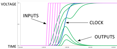
     (click to zoom)

    This image (from Metastability and Synchronizers — A Tutorial) shows how the output varies depending on the timing of a transition of the input signal (relative to the clock). You notice that the output may briefly hover near the center briefly before settling to 0 or 1. In fact if the input edge is sufficiently ill-timed, the flip-flop cannot decide and ends up in a metastable state, balancing on the edge until random influences finally push it over.

    Metastability is generally highly undesirable in digital logic: functional behaviour of the rest of the circuit may become unpredictable, and power consumption increases greatly (in some cases leading to destruction). To deal with this, special synchronization circuits are needed.

    A very common structure consists of two consecutive flip-flops: the first may go occasionally go metastable, but it is designed to ensure its output will settle in time for the second flip-flop to sample it safely. This is ultimately the origin of the "two pulses" requirement you mention.

    Note that these things are all over the SoC, really lots of them (the cortex-A8 interrupt controller alone has 128 synchronizers: one for each irq input), but all clock signals are sufficiently fast that you'd never notice except by careful timing tests.  However, if you select TCLKIN as the functional clock for a timer, but instead of a clock you send individual pulses, such delays can suddenly become highly visible.

    Chris Pendleton said:
    I see the QEP counters (and GPIO control) lock up

    I'm assuming you mean an attempt to access the QEP counter locks up, not the counter itself?

    The explanation in this case is simple: all three modules are attached to the same L4 interconnect, which serializes all read/write requests. This means that as long as the timer module is stalling a write, later requests to any peripheral on the same interconnect will be stuck in some queue.

    It is possible btw to configure timeouts in the L4 interconnect to prevent this sort of thing from locking up the whole system (although this leaves communication with that module in an undefined state). I can give more details if desired.

  • Thank you very much for the explanation, Matthijs. After considering you answer, re-reading the AM335x tech reference, and deconstructing Starterware example code, I have managed to wrap my head around this problem. I now have a system that will not lock up the L4 interconnect, and starts counting on DMTimer after the initial 2 pulses have come in.

    Regards, Chris