This thread has been locked.

If you have a related question, please click the "Ask a related question" button in the top right corner. The newly created question will be automatically linked to this question.

RTOS/TMDSICE3359: Changing UART instance

Part Number: TMDSICE3359
Other Parts Discussed in Thread: PROFIBUS, SYSBIOS, ISO1050, ISO1176T

Tool/software: TI-RTOS

Please consider this issue report related to the bellow file. 

This files clearly describes the steps to carry out to use UART1 instead of UART0 in BeagleBone Black.
I been trying to do similar task in ICEV2AM3359 board.

  1. Prerequisites installed
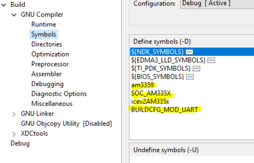
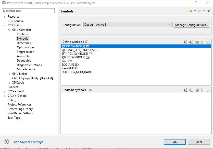
  2. software Modification
    1. opened TI cloud pinmux utility
    2. loaded "icev2_config" from C:\ti\pdk_am335x_1_0_7\packages\ti\starterware\tools\pinmux_config\am335x
    3. by default UART0, UART1, UART3 and UART4 are configured. In my case I wanted to use UART4 so I removed all UART except UART4
    4. generated files for staterware and downloaded it.
    5. Unzip the file. 
    6. At the bottom of am335x_pinmux.h, change extern pinmuxBoardCfg_t gAM335xPinmuxData[]; to extern pinmuxBoardCfg_t gIceV2PinmuxData[];
    7. Change am335x_pinmux_data.c to am335x_icev2_pinmux_data.c
    8. Change gAM335xPinmuxData to gIceV2PinmuxDataat the end of the file at pinmuxBoardCfg_t gAM335xPinmuxData[]= of  am335x_icev2_pinmux_data.c
    9. Replace the existing files with the new files in ${PDK_INSTALL_DIR}packages\ti\starterware\board\am335x.
  3. Power and clocking

Modify the PRCMModuleEnable() instance from UART0 to UART4 in the file ${PDK_INSTALL_DIR}\packages\ti\board\src\icev2AM335x\icev2AM335x.c.

To add peripheral instances,

  1. Change the UART instance in the file ${PDK_INSTALL_DIR}\packages\ti\board\src\bbbAM335x\include\board_cfg.h from 0 to 4 #define BOARD_UART_INSTANCE 4
  2. Change the UART instance from 0 to 1 inside PINMUXModuleConfig() in file ${PDK_INSTALL_DIR}\packages\ti\board\src\bbbAM335x\bbbAM335x_pinmux.c.
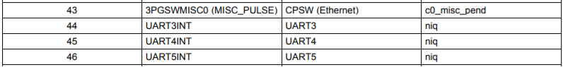
    status = PINMUXModuleConfig (CHIPDB_MOD_ID_UART, 4U, NULL)

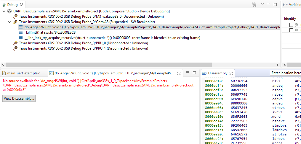
Rebuilded and executed. For my surprise still UART3 is running. Can any expert explain me if my steps are wrong. Thnak you.

Best regards

Vinay

  • The RTOS team have been notified. They will respond here.
  • Hello RTOS team,

    Can I quickly know, when a new uart project is created or using a example uart project the UART configuration and enabling is involved in only the listed files

    1. am335x_icev2_pinmux_data.c.
    2. ${PDK_INSTALL_DIR}\packages\ti\board\src\icev2AM335x\icev2AM335x.c
    3. ${PDK_INSTALL_DIR}\packages\ti\board\src\icev2AM335x\include\board_cfg.h
    4. ${PDK_INSTALL_DIR}\packages\ti\board\src\icev2AM335x\icev2AM335x_pinmux.c

    Is there any dependent file in which UART configuration are involved. Any changes to be done in CCS regarding this?

    Every time we create a new project with respect to UART and each project involves different UART then How to handle this?(Can we have separate PINMUX configuration for each project?)

    Thanks and I appreciate quick response.

    Regards

    Vinay

  • Any update on this thread is appreciated. Thank you!
  • Vinay,

    If you take a look the example C:\ti\pdk_am335x_1_0_10\packages\MyExampleProjects\UART_BasicExample_icev2AM335x_armExampleProject did you add the symbols as in the example into your CCS project properties?

    Also, did you rebuild the board library after you infused the changes you mentioned in the original post?

    Would be good to do a >gmake clean before a >gmake board.

    Lali

  • Lali,
    I did the both the point mentioned. that is adding symbols and i cleaned all and then rebuild all like gmake clean_all and then gmake all

    Did any of other test example held to test other UART?
    I followed the pin configuration steps, which you asked to refer a file. I know I"m missing out wit something very simple but unable to identify it. :-( from almost a month I'm stuck here and trying out too many things.

    Thanks hope some helpful hint/solution will be provided

    vinay
  • Hi Vinay, could you please let us know which error are you getting, or what is the behavior? Let's try to see if we can reproduce it

    thanks,
    Paula
  • I tried with 2 uarts (UART1 and UART4), but one at a time.

    Following are the connection/ pins used

    1. UART1 ----> D15 and D16 --> via pin 8 and 3 of Conn_DB9F(J9), also connected jumper to connect CAN_GND/PROFIBUS_A and PROFIBUS_A in J8.
    2. UART4 --> E18 and E17  ---> via pin 7 and 8 of 9X2 header J3

    Is the above connection correct to use UART1 and UART4?

    Steps performed for pin configuration

    1. For UART4
      1. Using TI pinmux cloud tool opened icev2_config which is present in local drive C:\ti\pdk_am335x_1_0_7\packages\ti\starterware\tools\pinmux_config\am335x
      2.  By default 4 UARTs was active/added. For my test I removed other three and retained UART4. UART4 by default using J18 and K15 pins. I changed to E18 and E17.
      3. Once I do this I get a conflict. As GPIO1_9 was also using E17. So I deselected GPIO1_9 to solve pin conflict.
      4. Under category selected atarterware and downloaded the files.
      5. am335x_pinmux_data.c file name changed to am335x_icev2_pinmux_data.c and gAM335xPinmuxData[] instance name change to gIceV2PinmuxData[].
      6. Also in am335x_pinmux.h, added all extern variable as shown bellow
        /* ========================================================================== */
        /*                            Global Variables                                */
        /* ========================================================================== */
        
        /** \brief Pinmux configuration data for the board. Auto-generated from
                   Pinmux tool. */
        extern pinmuxBoardCfg_t gGpevmPinmuxData[];
        
        /** \brief Pinmux configuration data for the board. Auto-generated from
                   Pinmux tool. */
        extern pinmuxBoardCfg_t gEvmskPinmuxData[];
        
        /** \brief Pinmux configuration data for the board. Auto-generated from
                   Pinmux tool. */
        extern pinmuxBoardCfg_t gBbPinmuxData[];
        
        /** \brief Pinmux configuration data for the board. Auto-generated from
                   Pinmux tool. */
        extern pinmuxBoardCfg_t gBbbPinmuxData[];
        
        /** \brief Pinmux configuration data for the board. Auto-generated from
                   Pinmux tool. */
        extern pinmuxBoardCfg_t gIceV1PinmuxData[];
        
        /** \brief Pinmux configuration data for the board. Auto-generated from
                   Pinmux tool. */
        extern pinmuxBoardCfg_t gIceV2PinmuxData[];
        
        /** \brief Pinmux configuration data for the board. Auto-generated from
                   Pinmux tool for IceV2, but with AMIC11x naming. Intended for
                   manual deviation from IceV2, if applicable. */
        extern pinmuxBoardCfg_t gAMIC11xPinmuxData[];

        I added all extern variable so the when I perform gmake all it won't break for other boards.

      7. In icev2AM335x.c under path C:\ti\pdk_am335x_1_0_7\packages\ti\board\src\icev2AM335x made following change to use only UART4
    /* UART */
    status = PRCMModuleEnable(CHIPDB_MOD_ID_UART, 4U, 0U);
    #if 0
    if(S_PASS == status)
    {
        status = PRCMModuleEnable(CHIPDB_MOD_ID_UART, 1U, 0U);
    }
    if(S_PASS == status)
    {
        status = PRCMModuleEnable(CHIPDB_MOD_ID_UART, 3U, 0U);
    }
    if(S_PASS == status)
    {
        status = PRCMModuleEnable(CHIPDB_MOD_ID_UART, 4U, 0U);
    }
    #endif

    h.  In board_cfg.h file from local path C:\ti\pdk_am335x_1_0_7\packages\ti\board\src\icev2AM335x\include changed #define BOARD_UART_INSTANCE             4
    i.  In icev2AM335x_pinmux.c under path C:\ti\pdk_am335x_1_0_7\packages\ti\board\src\icev2AM335x made following change to use only UART4

    /* UART */
    status = PINMUXModuleConfig(CHIPDB_MOD_ID_UART, 4U, NULL);
    #if 0
    if(S_PASS == status)
    {
        status = PINMUXModuleConfig(CHIPDB_MOD_ID_UART, 1U, NULL);
    }
    if(S_PASS == status)
    {
        status = PINMUXModuleConfig(CHIPDB_MOD_ID_UART, 3U, NULL);
    }
    if(S_PASS == status)
    {
        status = PINMUXModuleConfig(CHIPDB_MOD_ID_UART, 4U, NULL);
    }
    #endif


    After this opened command prompt in path C:\ti\pdk_am335x_1_0_7\packages
    • executed pdksetupenv.bat
    • gmake clean
    • gmake all
    • pdkProjectCreate.bat AM335x icev2AM335x little uart arm

    Finally opened CCS and imported UART_BasicExample_icev2AM335x_armExampleProject

    All expected symbols are present by default. Below is the image

    Rebuild it
    started to debug and run


    Please check am I missing any steps and are all the steps followed right.

    Please let me know any additional information required to reproduce this scenario

    Best regards

    Vinay


  • Hi Vinay, I was able to reproduce the issue. In my test, I didn't use Pinmux tool. I only changed BOARD_UART_INSTANCE and rebuild PDK (gmake clean, gmake all).
    If I use BOARD_UART_INSTANCE = 4, I got the same results, as you, in CCS (do_AngelSWI). In order to get more information, I enabled print errors in the project CCS .cfg file (am335x_app_icev2am335x.cfg). Below summary of changes in .cfg file:

    //Defaults.common$.diags_ASSERT = Diags.ALWAYS_OFF; //PC-- commented by
    //Error.raiseHook = null; //PC-- commented by
    //Text.isLoaded = false; //PC-- commented by
    //SysMin.flushAtExit = false; //PC-- commented by

    I also enable UIA in the .cfg, but I didn't used.. In anycase, here is what I added (just FYI)

    var LoggingSetup = xdc.useModule('ti.uia.sysbios.LoggingSetup');
    LoggingSetup.loadLogging = true;
    LoggingSetup.loadLoggerSize = 1024;
    LoggingSetup.mainLoggerSize = 32768;
    LoggingSetup.sysbiosLoggerSize = 32768;
    LoggingSetup.sysbiosSwiLogging = true;
    LoggingSetup.sysbiosHwiLogging = true;
    LoggingSetup.sysbiosSemaphoreLogging = true;
    LoggingSetup.loadTaskLogging = true;
    LoggingSetup.loadSwiLogging = true;
    LoggingSetup.loadHwiLogging = true;
    LoggingSetup.enableTaskProfiler = true;
    LoggingSetup.sysbiosHwiLoggingRuntimeControl = true;
    LoggingSetup.sysbiosSwiLoggingRuntimeControl = true;
    LoggingSetup.loggerType = LoggingSetup.LoggerType_STOPMODE;

    LoggingSetup.loadLoggingRuntimeControl = true;
    LoggingSetup.enableContextAwareFunctionProfiler = true;
    LoggingSetup.profileLogging = true;
    LoggingSetup.countingAndGraphingLogging = true;
    LoggingSetup.benchmarkLogging = true;
    LoggingSetup.snapshotLogging = true;

    After these changes, and rebuilding/running UART_BasicExample_icev2AM335x_armExampleProject, I saw in CCS command CIO window the following error:

    [CortxA8] {module#61}: line 142: E_badIntNum, intnum: 137 is out of range
    {module#61}: line 223: E_handleNotFound: Hwi handle not found: 0x8002cfb0
    xdc.runtime.Error.raise: terminating execution

    For some reason, the interrupt number used by UART instance 4 shows "out of range". I need to check if this is a bug, or if we need to configure something else for UART instance 4.

    As test, I change BOARD_UART_INSTANCE to 1 (inside board_cfg.h). UART instance 1 uses Interrupt number 105 (uartInitCfg inside UART_soc.c). After changing to instance 1, and rebuilding the project, I don't see the error anymore. Also I don't see anything printed in UART USB, so I think the change went OK.. Need to add an scope to confirm..

    In any case, I hope these debug trick are helpful, for more tricks and tips please visit: Processor SDK RTOS: TI RTOS Tips And Tricks

    thank you,

    Paula

  • Hi Paula,

    Looking forward to know are you able to read or write once you probe via oscilloscope. With respect to UART1 I used D15 and D16 --> via pin 8 and 3 of Conn_DB9F(J9), also connected jumper to connect CAN_GND/PROFIBUS_A and PROFIBUS_A in J8. Please also confirm are you making any hardware/software changes. Thank you!

    regards
    Vinay
  • Can u confirm which package you are using?
    I tried with pdk_am335x_1_0_7.
  • Paula, When I perform exactly like your experiment the thread will be running but no output in the terminal. I suspended/paused the debug to check which function is executing its always running ti_sysbios_family_arm_a8_intcps_Hwi_disable() repeatedly.

    Find the screen shot bellow.

    Is this same at your end too?

    vinay

  • My doubt/assumption is the UART interrupt routines are not mapped properly in the example project. It is mapped properly only to UART3 instance.
    Can anyone explain how and in which file interrupt for UART communication are defined and mapped?

    @Paula can you please give some information regarding UART TX and RX ISR? Hope that helps.
    Thank you!

    regards
    Vinay
  • Hi Vinay, let me see what I find.
    thank you,
    Paula
  • Hi Paula,

    When I was searching about the ISR for UART. I found the interrupt number for UART4 (137) and UART1 (105) in UART_soc.c file under local path C:\ti\pdk_am335x_1_0_7\packages\ti\drv\uart\soc\am335x\UART_soc.c

    But in interrupt.h file under local path C:\ti\AM335X_StarterWare_02_00_01_01\include\armv7a\am335x\interrupt.h the interrupt number are different.
    #define SYS_INT_UART1INT                       (73)

    #define SYS_INT_UART4INT                       (45)

    I thought interrupt number defined in UART_soc.c wrong and changed it to 73 and 45 for UART1 and UART4 respectively.

    Yet no positive outcome. I thing lot many changes with respect to interrupts are to be done. Can any UART driver developer can check with the interrupt for other UART instance once. Thank you!

    Hoping for quick response.

    Regards

    Vinay

  • Hi Vinay, no sure if you have seen this PSDK UART wiki, but in any case, below link for your reference:
    processors.wiki.ti.com/.../Processor_SDK_RTOS_UART

    Also, as a quick test, for UART4, I changed its interrupt number from 137 to 44 inside C:\TI\pdk_am335x_1_0_7\packages\ti\drv\uart\soc\am335x\UART_soc.c. I also changed UART3 to 137. In summary, I interchanged both UART's interrupt numbers.

    I also changed BOARD_UART_INSTANCE = 4 inside C:\TI\pdk_am335x_1_0_7\packages\ti\board\src\icev2AM335x\include\board_cfg.h, and rebuild PDK drivers (gmake clean, gmake all), and rebuilt application.

    Now, UART_BasicExample_icev2AM335x_armExampleProject seems to run OK, however, I don't have an FTDI cable to test it. I was wondering if you have one, if so, please give a try connecting J3 pins 7 and 8 (UART4) and let me know if it works.

    Thank you,
    Paula
  • Hi Paula,

    With UART4 I didn't test after changing interrupt number. By the way I I use FTDI module (also used oscilloscope).

    I will be back on Tuesday and then test and confirm you. Thank you!

    Please provide some update on UART1 too.

    Vinay

  • Hi Vinay, let me do some suggestions

    1) If possible use latest PSDK 4.3 which includes PDK 1.0.10. This latest PDK fixed UART interrupt number accordingly with AM335x TRM

    From there we have UART4 interrupt is actually 45


    2) Change instance number, as before: 

    #define BOARD_UART_INSTANCE 4  (C:\TI\pdk_am335x_1_0_10\packages\ti\board\src\icev2AM335x\include\board_cfg.h)

    3) Instead of rebuilding the whole PDK, you can rebuild only board library (quicker). I also suggest to check that C:\TI\pdk_am335x_1_0_10\packages\ti\board\lib\icev2AM335x\a8\release\ti.board.aa8fg is actually rebuild (check timestamp)

    > gmake board_lib

    4) Confirm in CCS project properties, that UART_BasicExample_icev2AM335x_armExampleProject is using PDK 1.0.10, and rebuild the project.

    Hope this helps,

    Paula

  • Hi Paula, I installed latest PSDK 4.3 and followed the instruction you mentioned above. The response/output is still same.

    When I connect the FTDI module to Pin 7 and 8 of J3 9X2 header following is the debug output when I pause/suspend the run.

    It continuously execute ti_sysbios_family_arm_a8_intcps_Hwi_disable() and ti_sysbios_family_arm_a8_intcps_Hwi_enable() APIs.
    Please confirm did you/other employee connect FTDI and tested the UART4 or UART1?

    Thank you for your continuous support. Hope your further guidance solves my issue.

    Regards

    Vinay

  • Hi Paula,

    As I mentioned I just installed PSDK 4.3 and changed instance number to 4 and rebuild only board_lib and recreated UART_BasicExample_icev2AM335x_armExampleProject in C:\ti\pdk_am335x_1_0_10\packages. compiled and executed. As I mentioned in the above post Hwi_enable and Hwi_disable() function executing repeatedly.

    In one of my post I mention that by default UART4 TX and RX pins are assigned to J18 and K15. So following are the changes I made to use pins 7 and 8 of J3 female header

    Please check the following.

    •  Used TI pinmux tool to generate uart pin configuration. Used E18 and E17 for UART4. commented previous UART4 config and added the new generated code. Please check bellow.
    static pinmuxPerCfg_t gUart4PinCfg[] =
    {
    	#if 0
        {
            /* UART 4 -> uart4_rxd -> J18 */
            PIN_GMII1_TXD3, 0, \
            ( \
                PIN_MODE(3) | \
                ((PIN_PULL_TYPE_SEL | PIN_RX_ACTIVE) & (~PIN_PULL_UD_EN)) \
            ) \
        },
        {
            /* UART 4 -> uart4_txd -> K15 */
            PIN_GMII1_TXD2, 0, \
            ( \
                PIN_MODE(3) | \
                ((PIN_PULL_TYPE_SEL) & (~PIN_PULL_UD_EN & ~PIN_RX_ACTIVE)) \
            ) \
        },
        {PINMUX_INVALID_PIN}
    	#endif
    	    {
           /* UART 4 -> uart4_rxd -> E18 */
           PIN_UART0_CTSN, 0, \
           ( \
               PIN_MODE(1) | \
               ((PIN_PULL_UD_EN | PIN_RX_ACTIVE) & (~PIN_PULL_TYPE_SEL)) \
           ) \
        },
        {
           /* UART 4 -> uart4_txd -> E17 */
           PIN_UART0_RTSN, 0, \
           ( \
               PIN_MODE(1) | \
               ((PIN_PULL_UD_EN) & (~PIN_PULL_TYPE_SEL & ~PIN_RX_ACTIVE)) \
           ) \
        },
        {PINMUX_INVALID_PIN}
    };

    • When i changed E17 for UART$_TXD i found its a conflict with GPIO1_9 so commented GPIO1_9 as shown bellow
    	#if 0
        {
            /* GPIO1 -> gpio1[9] -> E17 */
            PIN_UART0_RTSN, 9, \
            ( \
                PIN_MODE(7) | \
                ((PIN_PULL_UD_EN) & (~PIN_PULL_TYPE_SEL & ~PIN_RX_ACTIVE)) \
            ) \
        },
    	#endif
    • Now rebuild board_lib and tried but same result :-(

    Is i'm following right step?
    Please revert back as soon as possible. Thank you!

    Best regards

    Vinay

  • Hi Vinay, let us check and come back to you

    thank you,
    Paula
  • Hi Vinay, I was able to get UART4 working on J3 pin 7 and pin 8, after modifying C:\TI\pdk_am335x_1_0_10\packages\ti\starterware\board\am335x\am335x_icev2_pinmux_data.c


    Main changes are:


    1) In #if defined(BUILDCFG_MOD_UART) change UART4 from using J18 and K15, to use E17 and E18


    static pinmuxPerCfg_t gUart4PinCfg[] =
    {
        {
           /* UART 4 -> uart4_rxd -> E18 */
           PIN_UART0_CTSN, 0, \
           ( \
               PIN_MODE(1) | \
               ((PIN_PULL_UD_EN | PIN_RX_ACTIVE) & (~PIN_PULL_TYPE_SEL)) \
           ) \
        },
        {
           /* UART 4 -> uart4_txd -> E17 */
           PIN_UART0_RTSN, 0, \
           ( \
               PIN_MODE(1) | \
               ((PIN_PULL_UD_EN) & (~PIN_PULL_TYPE_SEL & ~PIN_RX_ACTIVE)) \
           ) \
        },
        {PINMUX_INVALID_PIN}
    };

    2) Delete gpio1[9] (which uses E17) inside gGpio1PinCfg[]

    3) Delete Sync0 and Sync1 inside gPru_icss1PinCfg[],as they use E17 and E18

    4) Clean and Rebuild PDK libraries

    5) Clean and Rebuild your CCS program

    6) Confirm FTDI connection and test

    FTDI orange -> UART4_RXD (J3 PIN 7)
    FTDI yellow -> UART4_TXD (J3 PIN 8)
    FTDI black -> GND (J3 PIN 2)

    I am attaching am335x_icev2_pinmux_data.c for your reference.

    thank you,
    Paula

    /**
     * Note: This file was auto-generated by TI PinMux on 2/23/2015 at 11:44:06 AM.
     *
     * \file  am335x_icev2_pinmux_data.c
     *
     * \brief  This file contains the pin mux configurations for the boards.
     *         These are prepared based on how the peripherals are extended on
     *         the boards.
     *
     * \copyright Copyright (CU) 2015 Texas Instruments Incorporated -
     *             http://www.ti.com/
     */
    
    /**
     *  Redistribution and use in source and binary forms, with or without
     *  modification, are permitted provided that the following conditions
     *  are met:
     *
     *    Redistributions of source code must retain the above copyright
     *    notice, this list of conditions and the following disclaimer.
     *
     *    Redistributions in binary form must reproduce the above copyright
     *    notice, this list of conditions and the following disclaimer in the
     *    documentation and/or other materials provided with the
     *    distribution.
     *
     *    Neither the name of Texas Instruments Incorporated nor the names of
     *    its contributors may be used to endorse or promote products derived
     *    from this software without specific prior written permission.
     *
     *  THIS SOFTWARE IS PROVIDED BY THE COPYRIGHT HOLDERS AND CONTRIBUTORS
     *  "AS IS" AND ANY EXPRESS OR IMPLIED WARRANTIES, INCLUDING, BUT NOT
     *  LIMITED TO, THE IMPLIED WARRANTIES OF MERCHANTABILITY AND FITNESS FOR
     *  A PARTICULAR PURPOSE ARE DISCLAIMED. IN NO EVENT SHALL THE COPYRIGHT
     *  OWNER OR CONTRIBUTORS BE LIABLE FOR ANY DIRECT, INDIRECT, INCIDENTAL,
     *  SPECIAL, EXEMPLARY, OR CONSEQUENTIAL DAMAGES (INCLUDING, BUT NOT
     *  LIMITED TO, PROCUREMENT OF SUBSTITUTE GOODS OR SERVICES; LOSS OF USE,
     *  DATA, OR PROFITS; OR BUSINESS INTERRUPTION) HOWEVER CAUSED AND ON ANY
     *  THEORY OF LIABILITY, WHETHER IN CONTRACT, STRICT LIABILITY, OR TORT
     *  (INCLUDING NEGLIGENCE OR OTHERWISE) ARISING IN ANY WAY OUT OF THE USE
     *  OF THIS SOFTWARE, EVEN IF ADVISED OF THE POSSIBILITY OF SUCH DAMAGE.
     *
     */
    
    /* ========================================================================== */
    /*                             Include Files                                  */
    /* ========================================================================== */
    #include "types.h"
    #include "pinmux.h"
    #include "am335x_pinmux.h"
    
    /** Peripheral Pin Configurations */
    #ifndef BUILDCFG_MOD_UART
    #define BUILDCFG_MOD_UART
    #endif /* BUILDCFG_MOD_UART */
    
    #ifndef BUILDCFG_MOD_CPSW
    #define BUILDCFG_MOD_CPSW
    #endif /* BUILDCFG_MOD_CPSW */
    
    #ifndef BUILDCFG_MOD_GPMC
    #define BUILDCFG_MOD_GPMC
    #endif /* BUILDCFG_MOD_GPMC */
    
    #ifndef BUILDCFG_MOD_GPIO
    #define BUILDCFG_MOD_GPIO
    #endif /* BUILDCFG_MOD_GPIO */
    
    #ifndef BUILDCFG_MOD_PRU_ICSS
    #define BUILDCFG_MOD_PRU_ICSS
    #endif /* BUILDCFG_MOD_PRU_ICSS */
    
    #ifndef BUILDCFG_MOD_I2C
    #define BUILDCFG_MOD_I2C
    #endif /* BUILDCFG_MOD_I2C */
    
    #ifndef BUILDCFG_MOD_MCSPI
    #define BUILDCFG_MOD_MCSPI
    #endif /* BUILDCFG_MOD_MCSPI */
    
    #ifndef BUILDCFG_MOD_MMCSD
    #define BUILDCFG_MOD_MMCSD
    #endif /* BUILDCFG_MOD_MMCSD */
    
    
    #if defined(BUILDCFG_MOD_UART)
    
    static pinmuxPerCfg_t gUart0PinCfg[] =
    {
        {
            /* UART 0 -> uart0_rxd -> E15 */
            PIN_UART0_RXD, 0, \
            ( \
                PIN_MODE(0) | \
                ((PIN_PULL_TYPE_SEL | PIN_RX_ACTIVE) & (~PIN_PULL_UD_EN)) \
            ) \
        },
        {
            /* UART 0 -> uart0_txd -> E16 */
            PIN_UART0_TXD, 0, \
            ( \
                PIN_MODE(0) | \
                ((PIN_PULL_TYPE_SEL) & (~PIN_PULL_UD_EN & ~PIN_RX_ACTIVE)) \
            ) \
        },
        {PINMUX_INVALID_PIN}
    };
    
    static pinmuxPerCfg_t gUart1PinCfg[] =
    {
        {
            /* UART1 -> uart1_rxd -> D16 */
            PIN_UART1_RXD, 0, \
            ( \
                PIN_MODE(0) | \
                ((PIN_PULL_TYPE_SEL | PIN_RX_ACTIVE) & (~PIN_PULL_UD_EN)) \
            ) \
        },
        {
            /* UART1 -> uart1_txd -> D15 */
            PIN_UART1_TXD, 0, \
            ( \
                PIN_MODE(0) | \
                ((PIN_PULL_TYPE_SEL) & (~PIN_PULL_UD_EN & ~PIN_RX_ACTIVE)) \
            ) \
        },
        {PINMUX_INVALID_PIN}
    };
    
    static pinmuxPerCfg_t gUart3PinCfg[] =
    {
        {
            /* UART3 -> uart3_rxd -> L17 */
            PIN_GMII1_RXD3, 0, \
            ( \
                PIN_MODE(1) | \
                ((PIN_PULL_TYPE_SEL | PIN_RX_ACTIVE) & (~PIN_PULL_UD_EN)) \
            ) \
        },
        {
            /* UART3 -> uart3_txd -> L16 */
            PIN_GMII1_RXD2, 0, \
            ( \
                PIN_MODE(1) | \
                ((PIN_PULL_TYPE_SEL) & (~PIN_PULL_UD_EN & ~PIN_RX_ACTIVE)) \
            ) \
        },
        {PINMUX_INVALID_PIN}
    };
    
    /*PC-- test, moving to ICEv2 board J3 pins 7 and 8 */
    static pinmuxPerCfg_t gUart4PinCfg[] =
    {
        {
           /* UART 4 -> uart4_rxd -> E18 */
           PIN_UART0_CTSN, 0, \
           ( \
               PIN_MODE(1) | \
               ((PIN_PULL_UD_EN | PIN_RX_ACTIVE) & (~PIN_PULL_TYPE_SEL)) \
           ) \
        },
        {
           /* UART 4 -> uart4_txd -> E17 */
           PIN_UART0_RTSN, 0, \
           ( \
               PIN_MODE(1) | \
               ((PIN_PULL_UD_EN) & (~PIN_PULL_TYPE_SEL & ~PIN_RX_ACTIVE)) \
           ) \
        },
        {PINMUX_INVALID_PIN}
    };
    
    static pinmuxModuleCfg_t gUartPinCfg[] =
    {
        {0, TRUE, gUart0PinCfg},
        {1, TRUE, gUart1PinCfg},
        {3, TRUE, gUart3PinCfg},
        {4, TRUE, gUart4PinCfg},
        {CHIPDB_INVALID_INSTANCE_NUM}
    };
    
    #endif /* if defined(BUILDCFG_MOD_UART) */
    
    #if defined(BUILDCFG_MOD_CPSW)
    
    static pinmuxPerCfg_t gCpsw0PinCfg[] =
    {
        {
            /* MDIO -> mdio_clk -> M18 */
            PIN_MDIO_CLK, 0, \
            ( \
                PIN_MODE(0) | \
                ((PIN_PULL_TYPE_SEL) & (~PIN_PULL_UD_EN & ~PIN_RX_ACTIVE)) \
            ) \
        },
        {
            /* MDIO -> mdio_data -> M17 */
            PIN_MDIO_DATA, 0, \
            ( \
                PIN_MODE(0) | \
                ((PIN_PULL_TYPE_SEL | PIN_RX_ACTIVE) & (~PIN_PULL_UD_EN)) \
            ) \
        },
        {
            /* RMII1 -> rmii1_crs_dv -> H17 */
            PIN_GMII1_CRS, 0, \
            ( \
                PIN_MODE(1) | \
                ((PIN_PULL_UD_EN | PIN_RX_ACTIVE) & (~PIN_PULL_TYPE_SEL)) \
            ) \
        },
        {
            /* RMII1 -> rmii1_rxer -> J15 */
            PIN_GMII1_RXER, 0, \
            ( \
                PIN_MODE(1) | \
                ((PIN_PULL_UD_EN | PIN_RX_ACTIVE) & (~PIN_PULL_TYPE_SEL)) \
            ) \
        },
        {
            /* RMII1 -> rmii1_txen -> J16 */
            PIN_GMII1_TXEN, 0, \
            ( \
                PIN_MODE(1) | \
                ((PIN_PULL_UD_EN) & (~PIN_PULL_TYPE_SEL & ~PIN_RX_ACTIVE)) \
            ) \
        },
        {
            /* RMII1 -> rmii1_txd0 -> K17 */
            PIN_GMII1_TXD0, 0, \
            ( \
                PIN_MODE(1) | \
                ((PIN_PULL_UD_EN) & (~PIN_PULL_TYPE_SEL & ~PIN_RX_ACTIVE)) \
            ) \
        },
        {
            /* RMII1 -> rmii1_txd1 -> K16 */
            PIN_GMII1_TXD1, 0, \
            ( \
                PIN_MODE(1) | \
                ((PIN_PULL_UD_EN) & (~PIN_PULL_TYPE_SEL & ~PIN_RX_ACTIVE)) \
            ) \
        },
        {
            /* RMII1 -> rmii1_rxd0 -> M16 */
            PIN_GMII1_RXD0, 0, \
            ( \
                PIN_MODE(1) | \
                ((PIN_PULL_UD_EN | PIN_RX_ACTIVE) & (~PIN_PULL_TYPE_SEL)) \
            ) \
        },
        {
            /* RMII1 -> rmii1_rxd1 -> L15 */
            PIN_GMII1_RXD1, 0, \
            ( \
                PIN_MODE(1) | \
                ((PIN_PULL_UD_EN | PIN_RX_ACTIVE) & (~PIN_PULL_TYPE_SEL)) \
            ) \
        },
        {
            /* RMII1 -> rmii1_refclk -> H18 */
            PIN_RMII1_REFCLK, 0, \
            ( \
                PIN_MODE(0) | \
                ((PIN_PULL_TYPE_SEL | PIN_RX_ACTIVE) & (~PIN_PULL_UD_EN)) \
            ) \
        },
        {
            /* RMII2 -> rmii2_crs_dv -> T17 */
            PIN_GPMC_WAIT0, 0, \
            ( \
                PIN_MODE(3) | \
                ((PIN_PULL_UD_EN | PIN_RX_ACTIVE) & (~PIN_PULL_TYPE_SEL)) \
            ) \
        },
        {
            /* RMII2 -> rmii2_rxer -> U17 */
            PIN_GPMC_WPN, 0, \
            ( \
                PIN_MODE(3) | \
                ((PIN_PULL_UD_EN | PIN_RX_ACTIVE) & (~PIN_PULL_TYPE_SEL)) \
            ) \
        },
        {
            /* RMII2 -> rmii2_txen -> R13 */
            PIN_GPMC_A0, 0, \
            ( \
                PIN_MODE(3) | \
                ((PIN_PULL_UD_EN) & (~PIN_PULL_TYPE_SEL & ~PIN_RX_ACTIVE)) \
            ) \
        },
        {
            /* RMII2 -> rmii2_txd0 -> V15 */
            PIN_GPMC_A5, 0, \
            ( \
                PIN_MODE(3) | \
                ((PIN_PULL_UD_EN) & (~PIN_PULL_TYPE_SEL & ~PIN_RX_ACTIVE)) \
            ) \
        },
        {
            /* RMII2 -> rmii2_txd1 -> R14 */
            PIN_GPMC_A4, 0, \
            ( \
                PIN_MODE(3) | \
                ((PIN_PULL_UD_EN) & (~PIN_PULL_TYPE_SEL & ~PIN_RX_ACTIVE)) \
            ) \
        },
        {
            /* RMII2 -> rmii2_rxd0 -> V17 */
            PIN_GPMC_A11, 0, \
            ( \
                PIN_MODE(3) | \
                ((PIN_PULL_UD_EN | PIN_RX_ACTIVE) & (~PIN_PULL_TYPE_SEL)) \
            ) \
        },
        {
            /* RMII2 -> rmii2_rxd1 -> T16 */
            PIN_GPMC_A10, 0, \
            ( \
                PIN_MODE(3) | \
                ((PIN_PULL_UD_EN | PIN_RX_ACTIVE) & (~PIN_PULL_TYPE_SEL)) \
            ) \
        },
        {
            /* RMII2 -> rmii2_refclk -> H16 */
            PIN_GMII1_COL, 0, \
            ( \
                PIN_MODE(1) | \
                ((PIN_PULL_TYPE_SEL | PIN_RX_ACTIVE) & (~PIN_PULL_UD_EN)) \
            ) \
        },
        {PINMUX_INVALID_PIN}
    };
    
    static pinmuxModuleCfg_t gCpswPinCfg[] =
    {
        {0, TRUE, gCpsw0PinCfg},
        {CHIPDB_INVALID_INSTANCE_NUM}
    };
    
    #endif /* if defined(BUILDCFG_MOD_CPSW) */
    
    #if defined(BUILDCFG_MOD_GPIO)
    
    static pinmuxPerCfg_t gGpio0PinCfg[] =
    {
        {
            /* GPIO0 -> gpio0[7] -> C18 */
            PIN_ECAP0_IN_PWM0_OUT, 7, \
            ( \
                PIN_MODE(7) | \
                ((PIN_PULL_TYPE_SEL) & (~PIN_PULL_UD_EN & ~PIN_RX_ACTIVE)) \
            ) \
        },
        {
            /* GPIO0 -> gpio0[18] -> F16 */
            PIN_USB0_DRVVBUS, 18, \
            ( \
                PIN_MODE(7) | \
                ((PIN_PULL_UD_EN) & (~PIN_PULL_TYPE_SEL & ~PIN_RX_ACTIVE)) \
            ) \
        },
    	{
    		/* My GPIO 1 -> gpio0[16] -> J18 */
    		PIN_GMII1_TXD3, 16, \
    		( \
    			PIN_MODE(7) | \
    			((PIN_PULL_UD_EN | PIN_RX_ACTIVE) & (~PIN_PULL_TYPE_SEL)) \
    		) \
    	},
    	{
    		/* My GPIO 1 -> gpio0[17] -> K15 */
    		PIN_GMII1_TXD2, 17, \
    		( \
    			PIN_MODE(7) | \
    			((PIN_PULL_UD_EN | PIN_RX_ACTIVE) & (~PIN_PULL_TYPE_SEL)) \
    		) \
    	},
    	{
    		/* My GPIO 0 -> gpio0[7] -> C18 */
    		PIN_ECAP0_IN_PWM0_OUT, 7, \
    		( \
    			PIN_MODE(7) | \
    			((PIN_PULL_TYPE_SEL) & (~PIN_PULL_UD_EN & ~PIN_RX_ACTIVE)) \
    		) \
    	},
    	{
    		/* My GPIO 0 -> gpio0[16] -> J18 */
    		PIN_GMII1_TXD3, 16, \
    		( \
    			PIN_MODE(7) | \
    			((0x38) & (~PIN_PULL_UD_EN & ~PIN_PULL_TYPE_SEL & ~PIN_RX_ACTIVE)) \
    		) \
    	},
    	{
    		/* My GPIO 0 -> gpio0[17] -> K15 */
    		PIN_GMII1_TXD2, 17, \
    		( \
    			PIN_MODE(7) | \
    			((0x38) & (~PIN_PULL_UD_EN & ~PIN_PULL_TYPE_SEL & ~PIN_RX_ACTIVE)) \
    		) \
    	},
    	{
    		/* My GPIO 0 -> gpio0[18] -> F16 */
    		PIN_USB0_DRVVBUS, 18, \
    		( \
    			PIN_MODE(7) | \
    			((PIN_PULL_TYPE_SEL) & (~PIN_PULL_UD_EN & ~PIN_RX_ACTIVE)) \
    		) \
    	},
    	{
    		/* My GPIO 0 -> gpio0[19] -> A15 */
    		PIN_XDMA_EVENT_INTR0, 19, \
    		( \
    			PIN_MODE(7) | \
    			((0x38) & (~PIN_PULL_UD_EN & ~PIN_PULL_TYPE_SEL & ~PIN_RX_ACTIVE)) \
    		) \
    	},
    	{
    		/* My GPIO 0 -> gpio0[20] -> D14 */
    		PIN_XDMA_EVENT_INTR1, 20, \
    		( \
    			PIN_MODE(7) | \
    			((0x38) & (~PIN_PULL_UD_EN & ~PIN_PULL_TYPE_SEL & ~PIN_RX_ACTIVE)) \
    		) \
    	},
        {PINMUX_INVALID_PIN}
    };
    
    static pinmuxPerCfg_t gGpio1PinCfg[] =
    {
        {
            /* GPIO1 -> gpio1[30] -> U9 */
            PIN_GPMC_CSN1, 30, \
            ( \
                PIN_MODE(7) | \
                ((PIN_PULL_UD_EN) & (~PIN_PULL_TYPE_SEL & ~PIN_RX_ACTIVE)) \
            ) \
        },
    	{
    		/* My GPIO 1 -> gpio1[31] -> V9 */
    		PIN_GPMC_CSN2, 31, \
    		( \
    			PIN_MODE(7) | \
    			((0x38) & (~PIN_PULL_UD_EN & ~PIN_PULL_TYPE_SEL & ~PIN_RX_ACTIVE)) \
    		) \
    	},
    	{PINMUX_INVALID_PIN}
    };
    
    static pinmuxPerCfg_t gGpio2PinCfg[] =
    {
    	{
    		/* My GPIO 2 -> gpio2[5] -> T6 */
    		PIN_GPMC_BE0N_CLE, 5, \
    		( \
    			PIN_MODE(7) | \
    			((0x38) & (~PIN_PULL_UD_EN & ~PIN_PULL_TYPE_SEL & ~PIN_RX_ACTIVE)) \
    		) \
    	},
    	{PINMUX_INVALID_PIN}
    };
    
    static pinmuxPerCfg_t gGpio3PinCfg[] =
    {
    	{
    		/* My GPIO 3 -> gpio3[4] -> J17 */
    		PIN_GMII1_RXDV, 4, \
    		( \
    			PIN_MODE(7) | \
    			((0x38) & (~PIN_PULL_UD_EN & ~PIN_PULL_TYPE_SEL & ~PIN_RX_ACTIVE)) \
    		) \
    	},
    	{
    		/* My GPIO 3 -> gpio3[9] -> K18 */
    		PIN_GMII1_TXCLK, 9, \
    		( \
    			PIN_MODE(7) | \
    			((0x38) & (~PIN_PULL_UD_EN & ~PIN_PULL_TYPE_SEL & ~PIN_RX_ACTIVE)) \
    		) \
    	},
    	{
    		/* My GPIO 3 -> gpio3[10] -> L18 */
    		PIN_GMII1_RXCLK, 10, \
    		( \
    			PIN_MODE(7) | \
    			((0x38) & (~PIN_PULL_UD_EN & ~PIN_PULL_TYPE_SEL & ~PIN_RX_ACTIVE)) \
    		) \
    	},
    	{
    		/* My GPIO 3 -> gpio3[18] -> B12 */
    		PIN_MCASP0_ACLKR, 18, \
    		( \
    			PIN_MODE(7) | \
    			((PIN_PULL_TYPE_SEL) & (~PIN_PULL_UD_EN & ~PIN_RX_ACTIVE)) \
    		) \
    	},
        {
            /* GPIO3 -> gpio3[21] -> A14 */
            PIN_MCASP0_AHCLKX, 21, \
            ( \
                PIN_MODE(7) | \
                ((PIN_PULL_UD_EN) & (~PIN_PULL_TYPE_SEL & ~PIN_RX_ACTIVE)) \
            ) \
        },
    
    	{PINMUX_INVALID_PIN}
    };
    
    static pinmuxModuleCfg_t gGpioPinCfg[] =
    {
        {1, TRUE, gGpio1PinCfg},
        {2, TRUE, gGpio2PinCfg},
        {0, TRUE, gGpio0PinCfg},
        {3, TRUE, gGpio3PinCfg},
        {CHIPDB_INVALID_INSTANCE_NUM}
    };
    
    #endif /* if defined(BUILDCFG_MOD_GPIO) */
    #if defined(BUILDCFG_MOD_GPMC)
    
    static pinmuxPerCfg_t gGpmc0PinCfg[] =
    {
    	{
    		/* My GPMC 1 -> gpmc_csn0 -> V6 */
    		PIN_GPMC_CSN0, 0, \
    		( \
    			PIN_MODE(0) | \
    			((0x38) & (~PIN_PULL_UD_EN & ~PIN_PULL_TYPE_SEL & ~PIN_RX_ACTIVE)) \
    		) \
    	},
    	{
    		/* My GPMC 1 -> gpmc_advn_ale -> R7 */
    		PIN_GPMC_ADVN_ALE, 0, \
    		( \
    			PIN_MODE(0) | \
    			((0x38) & (~PIN_PULL_UD_EN & ~PIN_PULL_TYPE_SEL & ~PIN_RX_ACTIVE)) \
    		) \
    	},
    	{
    		/* My GPMC 1 -> gpmc_oen_ren -> T7 */
    		PIN_GPMC_OEN_REN, 0, \
    		( \
    			PIN_MODE(0) | \
    			((0x38) & (~PIN_PULL_UD_EN & ~PIN_PULL_TYPE_SEL & ~PIN_RX_ACTIVE)) \
    		) \
    	},
    	{
    		/* My GPMC 1 -> gpmc_wen -> U6 */
    		PIN_GPMC_WEN, 0, \
    		( \
    			PIN_MODE(0) | \
    			((0x38) & (~PIN_PULL_UD_EN & ~PIN_PULL_TYPE_SEL & ~PIN_RX_ACTIVE)) \
    		) \
    	},
    	{PINMUX_INVALID_PIN}
    };
    
    static pinmuxModuleCfg_t gGpmcPinCfg[] =
    {
        {0, TRUE, gGpmc0PinCfg},
        {CHIPDB_INVALID_INSTANCE_NUM}
    };
    
    #endif /* if defined(BUILDCFG_MOD_GPMC) */
    
    #if defined(BUILDCFG_MOD_PRU_ICSS)
    
    static pinmuxPerCfg_t gPru_icss1PinCfg[] =
    {
    	{
    		/* My UART_PRUSS1 1 -> pr1_uart0_rxd -> D16 */
    		PIN_UART1_RXD, (uint16_t)PINMUX_SS_PRU_ICSS_UART0, \
    		( \
    			PIN_MODE(5) | \
    			((PIN_PULL_UD_EN | PIN_RX_ACTIVE) & (~PIN_PULL_TYPE_SEL)) \
    		) \
    	},
    	{
    		/* My UART_PRUSS1 1 -> pr1_uart0_txd -> D15 */
    		PIN_UART1_TXD, (uint16_t)PINMUX_SS_PRU_ICSS_UART0, \
    		( \
    			PIN_MODE(5) | \
    			((0x38) & (~PIN_PULL_UD_EN & ~PIN_PULL_TYPE_SEL & ~PIN_RX_ACTIVE)) \
    		) \
    	},
    	{
    		/* My PRU_PRUSS1 1 -> pr1_pru0_pru_r30[5] -> C13 */
    		PIN_MCASP0_FSR, (uint16_t)PINMUX_SS_PRU_ICSS_PRU0, \
    		( \
    			PIN_MODE(5) | \
    			((0x38) & (~PIN_PULL_UD_EN & ~PIN_PULL_TYPE_SEL & ~PIN_RX_ACTIVE)) \
    		) \
    	},
    
    	{
    		/* My MDIO_PRUSS1 1 -> pr1_mdio_mdclk -> V12 */
    		PIN_GPMC_CLK, (uint16_t)PINMUX_SS_PRU_ICSS_MDIO, \
    		( \
    			PIN_MODE(5) | \
    			((PIN_PULL_TYPE_SEL) & (~PIN_PULL_UD_EN & ~PIN_RX_ACTIVE)) \
    		) \
    	},
    	{
    		/* My MDIO_PRUSS1 1 -> pr1_mdio_data -> T13 */
    		PIN_GPMC_CSN3, (uint16_t)PINMUX_SS_PRU_ICSS_MDIO, \
    		( \
    			PIN_MODE(5) | \
    			((PIN_PULL_TYPE_SEL | PIN_RX_ACTIVE) & (~PIN_PULL_UD_EN)) \
    		) \
    	},
    	{
    		/* My MII_PRUSS1 1 -> pr1_mii_mt1_clk -> R13 */
    		PIN_GPMC_A0, (uint16_t)PINMUX_SS_PRU_ICSS_MII1, \
    		( \
    			PIN_MODE(5) | \
    			((PIN_PULL_UD_EN | PIN_RX_ACTIVE) & (~PIN_PULL_TYPE_SEL)) \
    		) \
    	},
    	{
    		/* My MII_PRUSS1 1 -> pr1_mii1_txd0 -> R14 */
    		PIN_GPMC_A4, (uint16_t)PINMUX_SS_PRU_ICSS_MII1, \
    		( \
    			PIN_MODE(5) | \
    			((0x38) & (~PIN_PULL_UD_EN & ~PIN_PULL_TYPE_SEL & ~PIN_RX_ACTIVE)) \
    		) \
    	},
    	{
    		/* My MII_PRUSS1 1 -> pr1_mii1_txd1 -> T14 */
    		PIN_GPMC_A3, (uint16_t)PINMUX_SS_PRU_ICSS_MII1, \
    		( \
    			PIN_MODE(5) | \
    			((0x38) & (~PIN_PULL_UD_EN & ~PIN_PULL_TYPE_SEL & ~PIN_RX_ACTIVE)) \
    		) \
    	},
    	{
    		/* My MII_PRUSS1 1 -> pr1_mii1_txd2 -> U14 */
    		PIN_GPMC_A2, (uint16_t)PINMUX_SS_PRU_ICSS_MII1, \
    		( \
    			PIN_MODE(5) | \
    			((0x38) & (~PIN_PULL_UD_EN & ~PIN_PULL_TYPE_SEL & ~PIN_RX_ACTIVE)) \
    		) \
    	},
    	{
    		/* My MII_PRUSS1 1 -> pr1_mii1_txd3 -> V14 */
    		PIN_GPMC_A1, (uint16_t)PINMUX_SS_PRU_ICSS_MII1, \
    		( \
    			PIN_MODE(5) | \
    			((0x38) & (~PIN_PULL_UD_EN & ~PIN_PULL_TYPE_SEL & ~PIN_RX_ACTIVE)) \
    		) \
    	},
    	{
    		/* My MII_PRUSS1 1 -> pr1_mii1_rxd0 -> V16 */
    		PIN_GPMC_A8, (uint16_t)PINMUX_SS_PRU_ICSS_MII1, \
    		( \
    			PIN_MODE(5) | \
    			((PIN_PULL_UD_EN | PIN_RX_ACTIVE) & (~PIN_PULL_TYPE_SEL)) \
    		) \
    	},
    	{
    		/* My MII_PRUSS1 1 -> pr1_mii1_rxd1 -> T15 */
    		PIN_GPMC_A7, (uint16_t)PINMUX_SS_PRU_ICSS_MII1, \
    		( \
    			PIN_MODE(5) | \
    			((PIN_PULL_UD_EN | PIN_RX_ACTIVE) & (~PIN_PULL_TYPE_SEL)) \
    		) \
    	},
    	{
    		/* My MII_PRUSS1 1 -> pr1_mii1_rxd2 -> U15 */
    		PIN_GPMC_A6, (uint16_t)PINMUX_SS_PRU_ICSS_MII1, \
    		( \
    			PIN_MODE(5) | \
    			((PIN_PULL_UD_EN | PIN_RX_ACTIVE) & (~PIN_PULL_TYPE_SEL)) \
    		) \
    	},
    	{
    		/* My MII_PRUSS1 1 -> pr1_mii1_rxd3 -> V15 */
    		PIN_GPMC_A5, (uint16_t)PINMUX_SS_PRU_ICSS_MII1, \
    		( \
    			PIN_MODE(5) | \
    			((PIN_PULL_UD_EN | PIN_RX_ACTIVE) & (~PIN_PULL_TYPE_SEL)) \
    		) \
    	},
    	{
    		/* My MII_PRUSS1 1 -> pr1_mii1_txen -> U17 */
    		PIN_GPMC_WPN, (uint16_t)PINMUX_SS_PRU_ICSS_MII1, \
    		( \
    			PIN_MODE(5) | \
    			((0x38) & (~PIN_PULL_UD_EN & ~PIN_PULL_TYPE_SEL & ~PIN_RX_ACTIVE)) \
    		) \
    	},
    	{
    		/* My MII_PRUSS1 1 -> pr1_mii_mr1_clk -> U16 */
    		PIN_GPMC_A9, (uint16_t)PINMUX_SS_PRU_ICSS_MII1, \
    		( \
    			PIN_MODE(5) | \
    			((PIN_PULL_UD_EN | PIN_RX_ACTIVE) & (~PIN_PULL_TYPE_SEL)) \
    		) \
    	},
    	{
    		/* My MII_PRUSS1 1 -> pr1_mii1_rxdv -> T16 */
    		PIN_GPMC_A10, (uint16_t)PINMUX_SS_PRU_ICSS_MII1, \
    		( \
    			PIN_MODE(5) | \
    			((PIN_PULL_UD_EN | PIN_RX_ACTIVE) & (~PIN_PULL_TYPE_SEL)) \
    		) \
    	},
    	{
    		/* My MII_PRUSS1 1 -> pr1_mii1_rxer -> V17 */
    		PIN_GPMC_A11, (uint16_t)PINMUX_SS_PRU_ICSS_MII1, \
    		( \
    			PIN_MODE(5) | \
    			((PIN_PULL_UD_EN | PIN_RX_ACTIVE) & (~PIN_PULL_TYPE_SEL)) \
    		) \
    	},
    	{
    		/* My MII_PRUSS1 1 -> pr1_mii1_rxlink -> U18 */
    		PIN_GPMC_BE1N, (uint16_t)PINMUX_SS_PRU_ICSS_MII1, \
    		( \
    			PIN_MODE(5) | \
    			((PIN_PULL_UD_EN | PIN_RX_ACTIVE) & (~PIN_PULL_TYPE_SEL)) \
    		) \
    	},
    	{
    		/* My MII_PRUSS1 1 -> pr1_mii1_crs -> R6 */
    		PIN_LCD_AC_BIAS_EN, (uint16_t)PINMUX_SS_PRU_ICSS_MII1, \
    		( \
    			PIN_MODE(2) | \
    			((PIN_PULL_UD_EN | PIN_RX_ACTIVE) & (~PIN_PULL_TYPE_SEL)) \
    		) \
    	},
    	{
    		/* My MII_PRUSS1 1 -> pr1_mii1_col -> T17 */
    		PIN_GPMC_WAIT0, (uint16_t)PINMUX_SS_PRU_ICSS_MII1, \
    		( \
    			PIN_MODE(5) | \
    			((PIN_RX_ACTIVE) & (~PIN_PULL_UD_EN & ~PIN_PULL_TYPE_SEL)) \
    		) \
    	},
    	{
    		/* My MII_PRUSS1 0 -> pr1_mii_mt0_clk -> R1 */
    		PIN_LCD_DATA0, (uint16_t)PINMUX_SS_PRU_ICSS_MII0, \
    		( \
    			PIN_MODE(2) | \
    			((PIN_PULL_UD_EN | PIN_RX_ACTIVE) & (~PIN_PULL_TYPE_SEL)) \
    		) \
    	},
    	{
    		/* My MII_PRUSS1 0 -> pr1_mii0_txd0 -> T2 */
    		PIN_LCD_DATA5, (uint16_t)PINMUX_SS_PRU_ICSS_MII0, \
    		( \
    			PIN_MODE(2) | \
    			((0x38) & (~PIN_PULL_UD_EN & ~PIN_PULL_TYPE_SEL & ~PIN_RX_ACTIVE)) \
    		) \
    	},
    	{
    		/* My MII_PRUSS1 0 -> pr1_mii0_txd1 -> T1 */
    		PIN_LCD_DATA4, (uint16_t)PINMUX_SS_PRU_ICSS_MII0, \
    		( \
    			PIN_MODE(2) | \
    			((0x38) & (~PIN_PULL_UD_EN & ~PIN_PULL_TYPE_SEL & ~PIN_RX_ACTIVE)) \
    		) \
    	},
    	{
    		/* My MII_PRUSS1 0 -> pr1_mii0_txd2 -> R4 */
    		PIN_LCD_DATA3, (uint16_t)PINMUX_SS_PRU_ICSS_MII0, \
    		( \
    			PIN_MODE(2) | \
    			((0x38) & (~PIN_PULL_UD_EN & ~PIN_PULL_TYPE_SEL & ~PIN_RX_ACTIVE)) \
    		) \
    	},
    	{
    		/* My MII_PRUSS1 0 -> pr1_mii0_txd3 -> R3 */
    		PIN_LCD_DATA2, (uint16_t)PINMUX_SS_PRU_ICSS_MII0, \
    		( \
    			PIN_MODE(2) | \
    			((0x38) & (~PIN_PULL_UD_EN & ~PIN_PULL_TYPE_SEL & ~PIN_RX_ACTIVE)) \
    		) \
    	},
    	{
    		/* My MII_PRUSS1 0 -> pr1_mii0_rxd0 -> U4 */
    		PIN_LCD_DATA11, (uint16_t)PINMUX_SS_PRU_ICSS_MII0, \
    		( \
    			PIN_MODE(5) | \
    			((PIN_PULL_UD_EN | PIN_RX_ACTIVE) & (~PIN_PULL_TYPE_SEL)) \
    		) \
    	},
    	{
    		/* My MII_PRUSS1 0 -> pr1_mii0_rxd1 -> U3 */
    		PIN_LCD_DATA10, (uint16_t)PINMUX_SS_PRU_ICSS_MII0, \
    		( \
    			PIN_MODE(5) | \
    			((PIN_PULL_UD_EN | PIN_RX_ACTIVE) & (~PIN_PULL_TYPE_SEL)) \
    		) \
    	},
    	{
    		/* My MII_PRUSS1 0 -> pr1_mii0_rxd2 -> U2 */
    		PIN_LCD_DATA9, (uint16_t)PINMUX_SS_PRU_ICSS_MII0, \
    		( \
    			PIN_MODE(5) | \
    			((PIN_PULL_UD_EN | PIN_RX_ACTIVE) & (~PIN_PULL_TYPE_SEL)) \
    		) \
    	},
    	{
    		/* My MII_PRUSS1 0 -> pr1_mii0_rxd3 -> U1 */
    		PIN_LCD_DATA8, (uint16_t)PINMUX_SS_PRU_ICSS_MII0, \
    		( \
    			PIN_MODE(5) | \
    			((PIN_PULL_UD_EN | PIN_RX_ACTIVE) & (~PIN_PULL_TYPE_SEL)) \
    		) \
    	},
    	{
    		/* My MII_PRUSS1 0 -> pr1_mii0_txen -> R2 */
    		PIN_LCD_DATA1, (uint16_t)PINMUX_SS_PRU_ICSS_MII0, \
    		( \
    			PIN_MODE(2) | \
    			((0x38) & (~PIN_PULL_UD_EN & ~PIN_PULL_TYPE_SEL & ~PIN_RX_ACTIVE)) \
    		) \
    	},
    	{
    		/* My MII_PRUSS1 0 -> pr1_mii_mr0_clk -> V4 */
    		PIN_LCD_DATA14, (uint16_t)PINMUX_SS_PRU_ICSS_MII0, \
    		( \
    			PIN_MODE(5) | \
    			((PIN_PULL_UD_EN | PIN_RX_ACTIVE) & (~PIN_PULL_TYPE_SEL)) \
    		) \
    	},
    	{
    		/* My MII_PRUSS1 0 -> pr1_mii0_rxdv -> T5 */
    		PIN_LCD_DATA15, (uint16_t)PINMUX_SS_PRU_ICSS_MII0, \
    		( \
    			PIN_MODE(5) | \
    			((PIN_PULL_UD_EN | PIN_RX_ACTIVE) & (~PIN_PULL_TYPE_SEL)) \
    		) \
    	},
    	{
    		/* My MII_PRUSS1 0 -> pr1_mii0_rxer -> V3 */
    		PIN_LCD_DATA13, (uint16_t)PINMUX_SS_PRU_ICSS_MII0, \
    		( \
    			PIN_MODE(5) | \
    			((PIN_PULL_UD_EN | PIN_RX_ACTIVE) & (~PIN_PULL_TYPE_SEL)) \
    		) \
    	},
    	{
    		/* My MII_PRUSS1 0 -> pr1_mii0_rxlink -> V2 */
    		PIN_LCD_DATA12, (uint16_t)PINMUX_SS_PRU_ICSS_MII0, \
    		( \
    			PIN_MODE(5) | \
    			((PIN_PULL_UD_EN | PIN_RX_ACTIVE) & (~PIN_PULL_TYPE_SEL)) \
    		) \
    	},
    	{
    		/* My MII_PRUSS1 0 -> pr1_mii0_crs -> V5 */
    		PIN_LCD_PCLK, (uint16_t)PINMUX_SS_PRU_ICSS_MII0, \
    		( \
    			PIN_MODE(2) | \
    			((PIN_PULL_UD_EN | PIN_RX_ACTIVE) & (~PIN_PULL_TYPE_SEL)) \
    		) \
    	},
    	{
    		/* My ECAT_PRUSS1 1 -> pr1_edio_data_out7 -> V9 */
    		PIN_GPMC_CSN2, (uint16_t)PINMUX_SS_PRU_ICSS_ECAT, \
    		( \
    			PIN_MODE(4) | \
    			((0x38) & (~PIN_PULL_UD_EN & ~PIN_PULL_TYPE_SEL & ~PIN_RX_ACTIVE)) \
    		) \
    	},
    	{PINMUX_INVALID_PIN}
    };
    
    static pinmuxModuleCfg_t gPru_icssPinCfg[] =
    {
        {1, TRUE, gPru_icss1PinCfg},
        {CHIPDB_INVALID_INSTANCE_NUM}
    };
    
    #endif /* if defined(BUILDCFG_MOD_PRU_ICSS) */
    
    #if defined(BUILDCFG_MOD_I2C)
    
    static pinmuxPerCfg_t gI2c0PinCfg[] =
    {
        {
            /* I2C 0 -> I2C0_SCL -> C16 */
            PIN_I2C0_SCL, 0, \
            ( \
                PIN_MODE(0) | \
                ((PIN_PULL_UD_EN | PIN_RX_ACTIVE) & (~PIN_PULL_TYPE_SEL)) \
            ) \
        },
        {
            /* I2C 0 -> I2C0_SDA -> C17 */
            PIN_I2C0_SDA, 0, \
            ( \
                PIN_MODE(0) | \
                ((PIN_PULL_UD_EN | PIN_RX_ACTIVE) & (~PIN_PULL_TYPE_SEL)) \
            ) \
        },
        {PINMUX_INVALID_PIN}
    };
    
    static pinmuxModuleCfg_t gI2cPinCfg[] =
    {
        {0, TRUE, gI2c0PinCfg},
        {CHIPDB_INVALID_INSTANCE_NUM}
    };
    
    #endif /* if defined(BUILDCFG_MOD_I2C) */
    
    #if defined(BUILDCFG_MOD_MCSPI)
    
    static pinmuxPerCfg_t gMcspi0PinCfg[] =
    {
    	{
    		/* My SPI 0 -> spi0_sclk -> A17 */
    		PIN_SPI0_SCLK, 0, \
    		( \
    			PIN_MODE(0) | \
    			((PIN_PULL_UD_EN | PIN_RX_ACTIVE) & (~PIN_PULL_TYPE_SEL)) \
    		) \
    	},
    	{
    		/* My SPI 0 -> spi0_d0 -> B17 */
    		PIN_SPI0_D0, 0, \
    		( \
    			PIN_MODE(0) | \
    			((PIN_PULL_UD_EN | PIN_RX_ACTIVE) & (~PIN_PULL_TYPE_SEL)) \
    		) \
    	},
    	{
    		/* My SPI 0 -> spi0_d1 -> B16 */
    		PIN_SPI0_D1, 0, \
    		( \
    			PIN_MODE(0) | \
    			((0x38) & (~PIN_PULL_UD_EN & ~PIN_PULL_TYPE_SEL & ~PIN_RX_ACTIVE)) \
    		) \
    	},
    	{
    		/* My SPI 0 -> spi0_cs0 -> A16 */
    		PIN_SPI0_CS0, 0, \
    		( \
    			PIN_MODE(0) | \
    			((0x38) & (~PIN_PULL_UD_EN & ~PIN_PULL_TYPE_SEL & ~PIN_RX_ACTIVE)) \
    		) \
    	},
    	{
    		/* My SPI 0 -> spi0_cs1 -> C15 */
    		PIN_SPI0_CS1, 0, \
    		( \
    			PIN_MODE(0) | \
    			((PIN_PULL_UD_EN | PIN_RX_ACTIVE) & (~PIN_PULL_TYPE_SEL)) \
    		) \
    	},
    	{PINMUX_INVALID_PIN}
    };
    static pinmuxPerCfg_t gMcspi1PinCfg[] =
    {
        {
           /* SPI1 -> spi1_sclk -> A13 */
           PIN_MCASP0_ACLKX, 0, \
           ( \
               PIN_MODE(3) | \
               ((PIN_PULL_UD_EN | PIN_RX_ACTIVE) & (~PIN_PULL_TYPE_SEL)) \
           ) \
        },
        {
           /* SPI1 -> spi1_d0 -> B13 */
           PIN_MCASP0_FSX, 0, \
           ( \
               PIN_MODE(3) | \
               ((PIN_PULL_UD_EN | PIN_RX_ACTIVE) & (~PIN_PULL_TYPE_SEL)) \
           ) \
        },
        {
           /* SPI1 -> spi1_d1 -> D12 */
           PIN_MCASP0_AXR0, 0, \
           ( \
               PIN_MODE(3) | \
               ((PIN_PULL_TYPE_SEL | PIN_RX_ACTIVE) & (~PIN_PULL_UD_EN)) \
           ) \
        },
        {
           /* SPI1 -> spi1_cs0 -> C12 */
           PIN_MCASP0_AHCLKR, 0, \
           ( \
               PIN_MODE(3) | \
               ((PIN_PULL_TYPE_SEL | PIN_RX_ACTIVE) & (~PIN_PULL_UD_EN)) \
           ) \
        },
        {PINMUX_INVALID_PIN}
    };
    
    static pinmuxModuleCfg_t gMcspiPinCfg[] =
    {
        {0, TRUE, gMcspi0PinCfg},
        {1, TRUE, gMcspi1PinCfg},
        {CHIPDB_INVALID_INSTANCE_NUM}
    };
    
    #endif /* if defined(BUILDCFG_MOD_SPI) */
    #if defined(BUILDCFG_MOD_MMCSD)
    
    static pinmuxPerCfg_t gMmcsd0PinCfg[] =
    {
        {
            /* MMC 0 -> mmc0_clk -> G17 */
            PIN_MMC0_CLK, 0, \
            ( \
                PIN_MODE(0) | \
                ((PIN_PULL_TYPE_SEL | PIN_RX_ACTIVE) & (~PIN_PULL_UD_EN)) \
            ) \
        },
        {
            /* MMC 0 -> mmc0_cmd -> G18 */
            PIN_MMC0_CMD, 0, \
            ( \
                PIN_MODE(0) | \
                ((PIN_PULL_TYPE_SEL | PIN_RX_ACTIVE) & (~PIN_PULL_UD_EN)) \
            ) \
        },
        {
            /* MMC 0 -> mmc0_dat0 -> G16 */
            PIN_MMC0_DAT0, 0, \
            ( \
                PIN_MODE(0) | \
                ((PIN_PULL_TYPE_SEL | PIN_RX_ACTIVE) & (~PIN_PULL_UD_EN)) \
            ) \
        },
        {
            /* MMC 0 -> mmc0_dat1 -> G15 */
            PIN_MMC0_DAT1, 0, \
            ( \
                PIN_MODE(0) | \
                ((PIN_PULL_TYPE_SEL | PIN_RX_ACTIVE) & (~PIN_PULL_UD_EN)) \
            ) \
        },
        {
            /* MMC 0 -> mmc0_dat2 -> F18 */
            PIN_MMC0_DAT2, 0, \
            ( \
                PIN_MODE(0) | \
                ((PIN_PULL_TYPE_SEL | PIN_RX_ACTIVE) & (~PIN_PULL_UD_EN)) \
            ) \
        },
        {
            /* MMC 0 -> mmc0_dat3 -> F17 */
            PIN_MMC0_DAT3, 0, \
            ( \
                PIN_MODE(0) | \
                ((PIN_PULL_TYPE_SEL | PIN_RX_ACTIVE) & (~PIN_PULL_UD_EN)) \
            ) \
        },
        {PINMUX_INVALID_PIN}
    };
    
    static pinmuxModuleCfg_t gMmcsdPinCfg[] =
    {
        {0, TRUE, gMmcsd0PinCfg},
        {CHIPDB_INVALID_INSTANCE_NUM}
    };
    
    #endif /* if defined(BUILDCFG_MOD_MMCSD) */
    
    /** EVM pin configurations for EVM */
    
    pinmuxBoardCfg_t gIceV2PinmuxData[] =
    {
    #if defined(BUILDCFG_MOD_UART)
        {CHIPDB_MOD_ID_UART, gUartPinCfg},
    #endif /* if defined(BUILDCFG_MOD_UART) */
    #if defined(BUILDCFG_MOD_CPSW)
        {CHIPDB_MOD_ID_CPSW, gCpswPinCfg},
    #endif /* if defined(BUILDCFG_MOD_CPSW) */
    
    #if defined(BUILDCFG_MOD_GPMC)
    	{CHIPDB_MOD_ID_GPMC, gGpmcPinCfg},
    #endif /* if defined(BUILDCFG_MOD_GPMC) */
    #if defined(BUILDCFG_MOD_GPIO)
        {CHIPDB_MOD_ID_GPIO, gGpioPinCfg},
    #endif /* if defined(BUILDCFG_MOD_GPIO) */
    #if defined(BUILDCFG_MOD_PRU_ICSS)
    	{CHIPDB_MOD_ID_PRU_ICSS, gPru_icssPinCfg},
    #endif /* if defined(BUILDCFG_MOD_PRU_ICSS) */
    #if defined(BUILDCFG_MOD_I2C)
        {CHIPDB_MOD_ID_I2C, gI2cPinCfg},
    #endif /* if defined(BUILDCFG_MOD_I2C) */
    #if defined(BUILDCFG_MOD_MCSPI)
        {CHIPDB_MOD_ID_MCSPI, gMcspiPinCfg},
    #endif /* if defined(BUILDCFG_MOD_SPI) */
    #if defined(BUILDCFG_MOD_MMCSD)
        {CHIPDB_MOD_ID_MMCSD, gMmcsdPinCfg},
    #endif /* if defined(BUILDCFG_MOD_MMCSD) */
        {CHIPDB_MOD_ID_INVALID}
    };


  • Thank you so much Paula. It worked.

    Interrupt number in pdk_am335x_1_0_7 was wrongly mapped and corrected in pdk_am335x_1_0_10.

    I took care for setting E17 and E18 for UART for and removed GPIO1_9 pin in configuration earlier but was missing out with  Sync0 and Sync1 inside gPru_icss1PinCfg[].

    Now I will try the same with UART1 and keep you updated.

    Best regards
    Vinay Venu

  • My one important question is if i want to add an Interrupt for uart transmission or reception to this example project what are the steps to follow. I don't see any ISR in the project path. I believe its included in the library so please give me more details on this. Thank you!
  • Hi Paula,

    Try with respect to <uart1 was not successful.

    Similar to the previous suggestion, I deleted pr1_uart0_rxd and pr1_uart0_txd as it was using D16 and D 15 respectively.

    Rebuild completely, that is >gmake clean and gmake all.

    To be double sure i completely deleted gPru_icss1PinCfg[] and variables using it to make sure that UART1 is not used by any other device/peripheral. If you look at the schematics there are  4 jumpers for CAN /PROFIBUS SELECTION.

    As UART1 is accessible from profibus i used J8 to select profibus(shorting profibus_a and can_gnd/profibus_a)

    Is the above steps right? any additional configuration with respect to hardware or pinmux required?


    intention is to use 3 and 8 pin of conn_DB9F.


    Thanks and regards

    vinay

  • Please give some information/solution. So I can efficiently utilize this weekend by working on it. Thank you!
  • Hi Vinay, no sure if you have seen below wiki

    From there, I See Read/Write APIs (interrupt mode) are as shown below:

    UART_read(handle,scanPrompt, sizeof(scanPrompt));/* Read API */
    ...
    UART_write(handle, bufferPrompt, sizeof(bufferPrompt));/* Write API */

    Or

    UART_transactionInit(&transaction);
    transaction.buf = (void *)scanPrompt;
    transaction.count = sizeof(scanPrompt);
    UART_read2(uart, &transaction);
    ...
    UART_transactionInit(&transaction);
    transaction.buf = (void *)bufferPrompt;
    transaction.count = sizeof(bufferPrompt);
    UART_write2(uart, &transaction);

    Looking for these APIs could help you to understand the code flow. after code inspections, If you still have any question, please let us know  

    thank you,

    Paula

  • Hi Paula,

    I have gone through those APIs.I think you didn't understand my question. Following are few important things I'm not having clarity

    1. The above mentioned API run in interrupt mode. That is fine, but where is that interrupt routine which handles when  read/write API is called? ( Just like ti_sysbios_family_arm_a8_intcps_Hwi_disable() and ti_sysbios_family_arm_a8_intcps_Hwi_enable() APIs there will be UART interrupt APIs
    2. High priority question is How to use UART1/UART0 which is on Profibus/CAN line respectively. In my previous question I mentioned how I connected jumper J8 to use UART1 from pin8 and 3 of Conn_DB9F (Please confirm this connection is right or not?)
    3. When I try to debug I can not  step into APIs as it is libraries. what settings changes to be done to see source code while debugging?
    4. I'm quite sure even here in using UART1 there is another thing I should take care. I deleted My UART_PRUSS1 1 -> pr1_uart0_rxd -> D16 and My UART_PRUSS1 1 -> pr1_uart0_txd -> D15 in gPru_icss1PinCfg. gmake board_clean -> gmake board -> generated uart example project. No successin UART1. Next I deleted gPru_icss1PinCfg[] variable, gPru_icssPinCfg and {CHIPDB_MOD_ID_PRU_ICSS, gPru_icssPinCfg} in gIceV2PinmuxData then gmake board_clean, gmake board, generated uart example project yet no success.
    5. As I'm mentioning many times is the connection I made to J( jumper is valid for using UART1?

    Please address all the question. With respect to connection I made please check with the hardware specialist. Thank you!

    regards

    Vinay

  • Hi Paula,
    Sorry for rushing too much and expecting quick reply. I know in practical you will be having several tickets to handle. I been working on this module for quite a long time. I want to make some progress so I'm taking work to home. As tomorrow is holiday I want to work on this so any update on this thread will be appreciated. Thank you!

    Best regards
    Vinay
  • Hi Vinay, apologize for my late reply. Let me try to answer some of the questions, and I will come back later with the rest.

    First at all, could you please check you have Selected PAD configuration Mode0 for UART1_RXD/TXD pins?. Registers address to check below

    SOC_CONTROL_REGS (0x44E10000)
    SOC_CONTROL_REGS + 0x980 = 0x0;
    SOC_CONTROL_REGS + 0x984 = 0x0;

    Just FYI, PADCONFIG for UART1_RXD/TXD pins in Mode5 corresponds to PRI1_UART0_RXD/TXD. From code inspection in Processor SDK, it seems default Mode is 0, so you should be OK, but just want you to confirm.

    Q2) It seems correct to me that you connect J8 (pin 1 &2). But, for selecting profibus, you also need to connect J10 (pin1 &2) and J7 (pin 1&2) . For more details on Jumpers and J9 (DB9 connector) pins please go to:
    processors.wiki.ti.com/.../AM335x_Industrial_Communication_Engine_EVM_Rev2_1_HW_User_Guide

    My main concern, is that ICEv2 DB9 is used for Profibus, or CAN. And, it is connected to a Profibus transceiver (ISO1176T), or Can bus transceiver (ISO1050). I am not sure we have used (tested) it as an UART connection..

    Q3) You can add needed source drivers files ( from C:\TI\pdk_am335x_1_0_10\packages\ti\drv) to your CCS project, rebuild your project, and add breakpoints in the places you want to debug.

    Q4) If inspecting with a scope, do you have any activity in the pins?
  • Hi Paula,

    Performed following,

      1. I checked am335x_icev2_pinmux_data.c file, as you mentioned PIN_MODE(0) for UART1_RXD/TXD(D16 and D15).
      2. I also connected J10 and J7 as you suggested.

    No success. No changes in the pin when checked via scope. Are there any other tests or experiments I can carryout for this?

    Thank you!

    Best regards
    Vinay Venu

  • Hi Paula,

    Did you get any response from your internal team for this topic?

    Thank you!
    Regards
    vinay
  • Hi Vinay, I got some information from a colleague. First you can check RX as by default RX is enabled.
    www.electronicdesign.com/.../what-s-difference-between-rs-232-and-rs-485-serial-interfaces

    If you are using to connect to a PC, then RS232 to RS485 converter is required as signaling differs. This shall be ok if testing Modbus Serial master or other ICE board.

    For transmit, TX_GPIO pin must be toggled.

    thank you,
    Paula
  • Hi Paula,
    For the same reason to toggle transmission enable pin I created e2e.ti.com/.../678887 thread. I want to know index of that pin to use GPIO toggle API

    Meanwhile I will try just receive and yeah I'm using RS485 to USB adapter to connect to PC.

    Regards
    Vinay