Because of the holidays, TI E2E™ design support forum responses will be delayed from Dec. 25 through Jan. 2. Thank you for your patience.

This thread has been locked.

If you have a related question, please click the "Ask a related question" button in the top right corner. The newly created question will be automatically linked to this question.

OPA1622: PCM512 + OPA1622 + BUF634

Part Number: OPA1622
Other Parts Discussed in Thread: BUF634,

Hi TI staff, 

 I would like to ask related question based on a thread "PCM512 + OPA1622 + BUF634" started by user..

My question refers to a schematic provided by TI staff member during the discussion. 

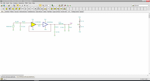
Question is, why there is a need for an additional resistor R2 at the OPA1622 noninverting input right after the R1 resistor. Also what is the role of the components set at the output of BUF634BUF634 (R4+C2, Lt and Ct). How do the effect the sound? 

Regards, 
  • Sorry to indicate a wrong original thread title. 

  • Jahongir,

    Resistor R2 is there to protect the input from over current scenarios. I would recommend it on the other input as well due to possible inductive kickbacks. The components Lt and Ct are modeling the cable LC. The 8 ohms is the speaker impedance. R4 and C4 are forming a snubber which is a circuit to suppress voltage transients such as inductive kickback. An inductive kickback will produce a sharp voltage rise dv/dt and the capacitor at high frequency will short to ground at AC and snub the transient therefore protecting the devices it is connected to. The capacitor is an open at DC so the device will see no DC loading from R4.