Hi Team,
If using Pin 31 and 32 as SRC4382 as AES output, how to use Pin 35 and 36 or how to configure Pin 35 and 36?
BR
Gust
This thread has been locked.
If you have a related question, please click the "Ask a related question" button in the top right corner. The newly created question will be automatically linked to this question.
Hi Team,
If using Pin 31 and 32 as SRC4382 as AES output, how to use Pin 35 and 36 or how to configure Pin 35 and 36?
BR
Gust
Hi Gust,
Pins 35 and 36 don't have to be used, but are optional and offer additional functionality. They can be used for the DIR or DIT as follows:
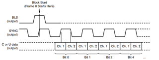
The AES3 encoder includes a block start input/output pin, BLS (pin 35). The BLS pin may be programmed as an input or output. The input/output state of the BLS pin is programmed using the BLSM bit in control register 0x07. By default, the BLS pin is configured as an input. As an input, the BLS pin may be utilized to force a block start condition, whereby the start of a new block of channel status and user data is initiated by generating a Z preamble for the next frame of data. The BLS input must be synchronized with the DIT internal SYNC clock. This clock is output on SYNC (pin 36). The SYNC clock rising edge is aligned with the start of each frame for the AES3-encoded data output by the DIT. Figure 66 illustrates the format required for an external block start signal, as well as indicating the format when the BLS pin is configured as an output. When the BLS pin is an output, the DIT generates the block start signal based upon the internal SYNC clock.
The channel status and user data bits may also be output serially through the general-purpose output pins, GPO[4:1]. Figure 71 illustrates the output format for the GPO pins when used for this purpose, along with the DIR block start (BLS) and frame synchronization (SYNC) clocks. The rising edges of the DIR SYNC clock output are aligned with the start of each frame for the received AES3 data.

Best,
Zak