This thread has been locked.

If you have a related question, please click the "Ask a related question" button in the top right corner. The newly created question will be automatically linked to this question.

TLV320AIC3268: MiniDSP BiQuad Coefficient Loading

Part Number: TLV320AIC3268

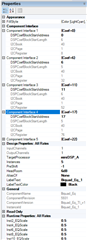
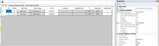
Using PurePath Studio I created a configuration that includes two instances of a BiQuad. One is a High Bandpass Filter and the second is a Low Bandpass Filter. A right click on the BiQuad object presents a menu with Help. Help says that each BiQuad instance contains a 20-byte block of coefficients a=B0, B1, B2, A1, and A2. At 4 bytes per coefficient, Help does not define the format of this 4-byte data structure. Is this a 1.31 structure or something else. Since PPS says one can modify these coefficients directly, I am assuming that no quantization (N0, N1, N2, D1, and D2) is required.

My questions: (a) What is the 4-byte data structure (format) for B0 through A2? (b) Is quantization necessary or can I just write the B0, B1, B2, A1, and A2 after being converted to necessary data structure.

Thank you in advance.

  • Hi Phil,

    If you are using the regular biquad then it will be in 1.23 format. If you use the extended precision biquad it will be 1.47. 

    B0, B2, and A2 can be written directly but B1 and A1 are multiplied by 2 and thus you should write 1/2 the original value. 

    Best,

    Zak

  • I have discovered that each coefficient utilizes 4 bytes. Of the four bytes, the first three are used and the last byte is zero. The first three bytes utilize a 1.23 format, as you stated. B0, B2, etc, must be normalized and scaled to be N0, N1, ..

    Now, the only problem is enabling the new coefficients when in adaptive filtering mode. There is no definition where the MiniDSP stores its Buffer A versus Buffer B locations. And, it is not entirely clear where you trigger the swap between the two buffers. I have studied SLAA425D but it only discusses concepts and not actual MiniDSP addressing. I am using the MiniDSP and not a processing block.  I have the same issue with the DRC coefficient locations. In fact, the only way I could find the address locations for the Buffer A location is by looking at the PPS generated script. The Buffer B location isn't clear.

  • Hey Phil,

    Yes this is correct. Each coefficient is allocated 4 bytes, but they are only 24-bit coefficients so that last byte is not needed. If you look at the addresses in PPS you will also notice that every other biquad includes an extra 4-byte coefficient. This is allocated to the EQ scaling between biquad instantiations to avoid overflow. So you would program the biquad coefficients in order of B0, B1, B2, A1, A2, EQscale (when applicable).

    For the adaptive filtering it actually doesn't matter so much what the locations of Buffer A and B are. Section 8.3.2.8.7 gives a pretty good description of this feature. While the device is running and adaptive filtering is enabled, coefficient updates are always made to the buffer that is not currently in use, regardless of which address has been written to. Thus, you can write to the same address used to initially program the biquads.

    Setting the control bit B40_P0_R1_D0=1 will switch the coefficient buffers at the next sampling period and will automatically revert to 0 after the switch occurs (so you could use it to monitor when the coefficients have finished updating)

    There is also a flag, B40_P0_R1_D1 that indicates which of the 2 buffers is currently active.

    If you did want to read the active coefficients back before writing to them the coefficient maps for buffers A and B are given in tables 54 and 55 for the ADC and tables 57 and 58 for the DAC. Note the map doesn't exhaust all coefficients, but shows the trend

    These coefficient numbers will correspond to the coefficient addresses assigned in PPS in the component interface table.

    Best,

    Zak

  • Zak,

    Thanks for verifying the info on the data format of the coefficients.

    Regarding the "component interface table" for the address assignments.

    I have two instances of a BiQuad. One is a HPF and the second a LPF. See image above.

    PPS shows the coefficient address of each instance.  Again, see image above and to the right.

    PPS does not show the location of the Buffer B addresses. This is key information that I need right now.

    In section 8.3.3.6.2, last paragraph, "The user programmable coefficients C1 to C70 are defined on B80_P1-P3 for Buffer A and B80_P9-P11 for Buffer B. For the Secondary Bank, the coefficients are located on the similar pages on Book 82."  Again, I don't know where the actual Buffer B is located. At least, I am not seeing this information.

    Thanks, Zak.

    Phil

  • I just re-read your message where you wrote, "While the device is running and adaptive filtering is enabled, coefficient updates are always made to the buffer that is not currently in use, regardless of which address has been written to. Thus, you can write to the same address used to initially program the biquads."

    So, I can use the same address that is listed in the component interface table (see image above)?  However, I should still toggle the Buffer flag?


  • Hey Phil,

    I don't think PPS bothers to mention the buffer B addresses because you don't really need them since the device will automatically switch to the buffer not currently being used whenever you write to either of the buffers, so it is sufficient to "write to buffer A" every time and if that's in use it will store the coefficients in buffer B. Thus there's only one set of addresses you have to deal with and you can use the flag to determine which buffer is currently active.

    If you'd prefer not to do that though then you can use the tables I mentioned. Buffer B is in the same book so the page and base registers are different, but they are still organized by the same coefficient names. So coefficient C0 in buffer A (book 40 page 1 register 8) would be mirrored by Buffer B C0 in book 40 page 9 register 72.

    The buffer flag is read only and used to determine which buffer is active, the control bit is what needs to be toggled to switch which buffer is active.

    Best,

    Zak

  • Thank you, Zak!  That helps a ton.

    For what it's worth, SLAA447 "Configure Coefficients for Digital Biquad Filters in the TLV320AIC3xxx Family", needs to be modified to clarify the data format and addressing when using the MiniDSP. It only addresses processing blocks (such as PRB_R5, PRB_P2, etc.) for configuration of biquad filters.

  • Hey Phil,

    Happy to help! Thanks for the feedback. Yeah I think part of the issue is that the AIC326x parts actually came out after the app note so they weren't technically included and while it functions largely the same, there are some differences. Hence the discrepancy in the coefficient bit depth. 

    I agree it would be helpful to have an app note that discusses I2C programming with the miniDSP enabled. At least in the interim your posts should serve as a good guide for those with similar goals!

    Best,

    Zak

  • You were correct. The chip automatically bounced between the buffers on its own. No pop or any noise effect when switching.