Dear TI support,
I try to use the internal tone generator of the TAS2562. Based on the datasheet, I made an analysis on the device configuration to generate a 1 kHz tone. However, I do not manage to get a signal at the output of the TAS2562. I use the TAS2562YFPEVM-DC evaluation module controlled by an STM32 microcontroller. I try to explain what I am doing, can you please point out what I am missing or doing wrong in my analysis?
1. HARDWARE
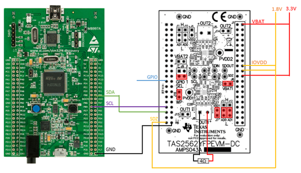
I made my setup as follows:
- The VBAT pin and 3.3V pin are supplied with 3.3V
- The IOVDD pin, the SDZ pin and 1.8V pin are supplied with 1.8V
- The jumpers are set to use device U1, as indicated in the image below
- The address of the TAS2562 is set to 0x98 by setting J12 and J13 to LOW
- I want to use the GPIO pin to enable/disable the tone
- My firmware runs on an STM32. Using the SDA and SCL lines, I am able to write to the internal registers of the TAS2562. This works correctly, since I can read the correct values from the registers after I have written them.

2. FIRMWARE
First, I configure the frequency and amplitude of the tone. This because the frequency and amplitude should be set only when the tone generator is disabled. The relevant registers are located at page 0x02 of the internal memory. Therefore, I set the PAGE register to 0x02:

I calculate and program the values for the tone frequency, with:
f_c: The desired frequency, i.e. 1 kHz.
f_s: The sampling rate. Since the tone generator is configured to operate in pin-triggered mode, the datasheet states that the sampling rate used in the TG1 equations should be 96 kHz.


I calculate and program the value for the tone amplitude, being the default value of A = -40 dBFS.

The next parameters to configure are located at page 0x00 of the internal memory. Therefore I set the PAGE register to 0x00:

The general configuration of the tone generator is done by setting the TG_CFG0 register to the value 0x20.
This disables tone generator 2 and enables pin-triggering for tone generator 1:

Writing the value 0x1 to bits 7-4 of the MISC_CFG4 register selects the internal oscillator as clock source:

Finally, I activate the tone generator by setting the operational mode to ACTIVE:
![]()
At the output of the amplifier, I cannot measure any signal except noise. Are the register values I calculated correct? Do I have to include other configurations? Can you please point out what I am missing or doing wrong in this analysis?
Regards,
Toon Daemen, Electronics engineer

