This thread has been locked.

If you have a related question, please click the "Ask a related question" button in the top right corner. The newly created question will be automatically linked to this question.

TAS2563: Documenting register values in the datasheet

Part Number: TAS2563

Hello,

I was looking at the data sheet on ways to adjust volume (DVC_PCM), and it looks like the register information is not present in the data sheet. I eventually found it in a post here on e2e: https://e2e.ti.com/support/audio-group/audio/f/audio-forum/928138/faq-tas2563-adjusting-digital-volume-control-using-i2c

So, my question is if this information will make it's way in the data sheet soon? Also couldn't find ways to access LIM_MAX_ATN, LIMB_TH_MAX registers. Is there other ways users usually set these values if they ever have to?

  • Hello,

    In regards to your first question, the data sheet will be updated in the next revision cycle. 

    Next, LIM_MAX_ATN is accessible through Book 0 Page 2, registers 0x14-0x17. LIMB_TH_MAX is accessible through Book 0 Page 2, registers 0x18-0x21. These are not in the data sheet, however, they are accessible through PPC3. Page 51 of the data sheet discusses how to calculate these values, however does not include the registers. Hopefully this information helps in regard to register access.

    Thank you,

    Elizabeth Weichel

  • Thank you for the quick response. Those were just some examples..wondering if I missed out on any other registers. How are these accessed outside of PPC by users, say in production software? PPC is a development tool only

  • Hello,

    This depends on wat you are using to send I2C commands. With Linux, you would need to use embedded commands for the I2C interface. With a microcontroller, there is typically a set of libraries for I2C commands. You can use single register commands (these are in the Direct I2C section of PPC3), or you can use register settings developed in the End System Integration panel of I2C that either generates .bin files or .h files.

    Thank you,

    Elizabeth Weichel

  • I believe I didn't frame my question correctly. My question is not about I2C implementation, but how would one set LIMB_TH_MAX or any other register value that is not documented in the datasheet. May be there is a way to find out via PPC? 

    Also that you mentioned .bin and header files, can you advise whether the .bin file combines information contained in the multiple header files that get generated when exported from PPC? I got around 4-5 header files but only one .bin file. The header files add up to quite a large size so I would prefer the bin file. Hence I'd like to confirm whether the bin file encapsulates all the information that is contained in the multiple header files.

  • Hi,

    I'm supporting here with the configuration files questions.
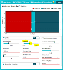
    Any register that is currently mentioned as reserved or not mentioned in the documentation, you can still configure it using PPC3, eg. LIMB_TH_MAX is set based on GUI Device Control panel:

    It is recommended to use GUI to set all required settings and then generate the configuration file either in bin, header or cfg. It will contain all required settings and will prevent any problems due to incorrect sequencing.

    Regarding the configuration files, bin file is OK, it has all your settings from Device Control and Tuning and Audio Processing panels, just make sure to always click the Apply button at Device Control panel to include those settings as well.
    The header files that you would need are"configuration_0_TuningMode_48KHz_DEV_A_COEFF.h" and "program_0_Tuning Mode.h", the files that say "calibration" are used for a different mode. COEFF file has the tuning settings and the other file has the rest of the configuration.

    Please let us know if you have any further questions.

    Best regards,
    - Ivan Salazar
    Applications Engineer

  • Thank you for the explainer, it was helpful! 
    I have some more questions, hope you can clarify - 
    The end systems integration guide has this line

    DSP program memory and coefficient memory are empty

    Does this mean that any attempted audio played will not play (ie no sound) or the sounds will not be at ideal performance in line with the speaker's capability?

    If you could help clarify on what these items are, or confirm if my understanding is correct:

    - DEV_A, DEV_B in the driver: are these for the two serial interfaces AS1/AS2?
    - "Program" - is this the DSP program? Is it different for different speaker profiles or just not pre-loaded on the chip? If I understand correctly, this is the program generated after the tuning procedure, and is present in the program_0_Tuning Mode.h file as well as the bin file? 

    - "Coefficients" - Are these the related to the speaker? How is it different from the "Program"

    - "Configuration" - This is Brown-Out Protection, Limiter, Boost control, and Thermal Foldback and other such register configuration?

    - "Calibration" - This is presumably for the factory configuration file, ie .ftcfg file? Is it expected to already be performed before the program/coefficients are loaded in? What kind of data does it hold that is not already present in the tuning program/coefficients?

    - The guide says "feed the PLL", but the driver doesn't do any PLL config (i.e. TAS2563_BLOCK_PLL is not used anywhere)

  • Hi,

    Let me follow up on your new questions:

    • If you simply enable the device using MODE bits from register 0x02, you will be able to play audio in what we call "ROM mode" which is a basic Class-D amplifier with digital input, no further processing or protection is applied.
    • No, DEV_A and DEV_B are the amplifier itself. If you set PPC3 to "Mono" you only have DEV_A, if you have "Dual Mono" you'll see both DEV_A and DEV_B
    • Coefficients are all the settings that go into the embedded DSP processor, this is basically all your configuration from "Tuning and Audio Processing" panel
    • Yes, similar to Coefficients above, the Configuration is basically all your settings from "Device Control" panel. This is considered "Hardware settings" and these are available even if not using the embedded DSP processor, eg. in ROM mode.
    • Calibration files are used only during FTC (Factory Test Calibration) this is an optional one-time test that can be performed during production process. The purpose of FTC is to calibrate each amplifier to the speaker attached to it at the end product, and update any part-to-part variation on the speaker parameters. (It will update the original speaker characterization parameters)
    • Usually the device is configured in Automatic mode, which detects sample rate and SBCLK to FSYNC ratio. so the PLL values are set automatically.as long as there is a valid set of clocks present at the digital interface.

    Let me know if you have further questions. If the questions end up being a different topic we may split the thread for better follow up.

    Best regards,
    -Ivan Salazar
    Applications Engineer

  • Thank you ! I believe this answers most of my questions, except what the "Program" does

  • Hi,

    I just double checked the verbiage and I think I understand your question:

    • Where I mentioned Configuration, it is Program instead
    • Configuration is just the selection of Mode, Sampling Frequency and Clock Configuration, as displayed in Figure 1-3

    The rest of the description remains the same, sorry for the confusion.

    Best regards,
    -Ivan Salazar
    Applications Engineer