Because of the Thanksgiving holiday in the U.S., TI E2E™ design support forum responses may be delayed from November 25 through December 2. Thank you for your patience.

This thread has been locked.

If you have a related question, please click the "Ask a related question" button in the top right corner. The newly created question will be automatically linked to this question.

TL972: spec check

Part Number: TL972
Other Parts Discussed in Thread: LM358, LT1013, TLV2376, TLV2333, LM358BA

Hi

Customers use TL972IDR For non-reverse amplification, the action is normal when using dual power supply V+=5V, V-=-5V (The voltage increases with the increase of my VIN)

But switch to a single power supply V+=5V, when V-=0V, the output is always 5V Is there a problem where it is used?

  • Hello Gareth,

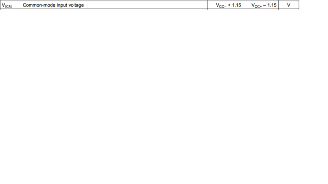
    The input stage of TL972 is not rail to rail. I suspect your input common mode is 0V. This is fine with supply -5V,+5V. It is not good for supply 0V,5V 

  • Hi Ron

    Customers currently test to lower the magnification (magnification: 2 times), the input 1-2V output has a magnification change

    Is it because of this parameter?

    If you can help me find one set of single power supply or two sets of OPs

    I input close to 0V-20mV can be amplified

    I have tried LM358 0-3mV, there is no change

    Are there any other suggested products?

  • Hey Gareth, 

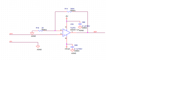
    Please post a schematic of your current setup.

    All the best,
    Carolina

  • Hi Caro

    The picture below shows the tested schematic Currently (VIN+)-(VIN-) is 5V from 0mV input to 30mV output

  • Gareth,

    If input signal full scale is 30mV then you need amplifier with an input offset error less than 0.3mV (1% of full scale) 

    https://www.ti.com/amplifier-circuit/op-amps/precision/products.html#p3318=10000;1258042&p480=2;2&p2max=0.0015;0.3&sort=p1130;asc

    For low cost , optimized for 5V (and lower), and availability, I suggest TLV2376 (faster) or TLV2333 (lower IQ). Almost all dual op amps have the same pinout  (for most packages). LT1013 is an exception.  

  • Hi Ron

    Thank you very much for your suggestions

    Can the input offset voltage be adjusted by correction? Because you recommend these two OPs, they should be one-level higher than the original TL972 I used. The customer changed to a single power supply for COST DOWN But this OP is twice as expensive Can you help me find VCM's (V-)-0.1 or above Just find the input offset voltage about mV first

  • Gareth,

    For offset correction (post amplifier, usually software), it is important that offset won't cause the output to reach maximum (VOL or VOH)

    So I lowered gain to 133 and output minimum is raised to 0.415V.

    A 3mV op amp offset will change the output by +/-3mV * 133 = +/-399mV

    So output could be range between 415mV - 399mV = 16mV to 4.403 + 399mV = 4.802V 

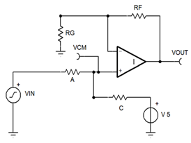
    Summary for circuit #2,  [A, C, V, RF, RG] solution, no [B, RH, VREF]
    Parameter Real Values Units Note
    A 165 Make Standard R choice
    C 264,000 Make Standard R choice
    V 5 Volt  
    RF 264,000 Make Standard R choice
    RG 2,000 Make Standard R choice
      
     
    Summary result Point 1 Point 2 Units
    VIN 0 0.03 Volt
    VOUT 0.415 4.403 Volt
    VCM 0.003 0.033 Volt

    This example could use LM358BA if the output doesn't have to sink current from VOUT load.