This thread has been locked.

If you have a related question, please click the "Ask a related question" button in the top right corner. The newly created question will be automatically linked to this question.

TPA2011D1: Correct measurement of max output power

Part Number: TPA2011D1

Hi support Team,

During Audio Amplifier test the 1kHz sinus I tried to amplify got cut of and I am not sure if I am measuring wrong or if the design is incorrect.

Schematic:

In bellow test R21 and R22 where changed to 200kOhm and R23 to 100kOhm to reduce Gain.
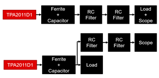
 

Test Setup:

- 4kOhm resistor connected between SPKR- and SPKR+

- Two times RC low-pass filter with RC-Filter Rf=1kOhm and Cf=4.7nF connected between SPKR- and GND_AUD and SPKR+ and GND_AUD

- Oscilloscope cannel1 connected to SPKR- between Rf- and Cf- as close as possible to Cf

- Oscilloscope cannel2 connected to SPKR+ between Rf+ and Cf+ as close as possible to Cf

- GND pins of cannel1 and 2 connected between Cf+/Cf- and GND_AUD as close as possibel to Cf


Test Procedure:

- Play 1kHz (0db) sine with Audio software with an HD audio codec and measure SPKR- and SPKR+

- Measure input voltage +V5 on C40 (AC-measurement)
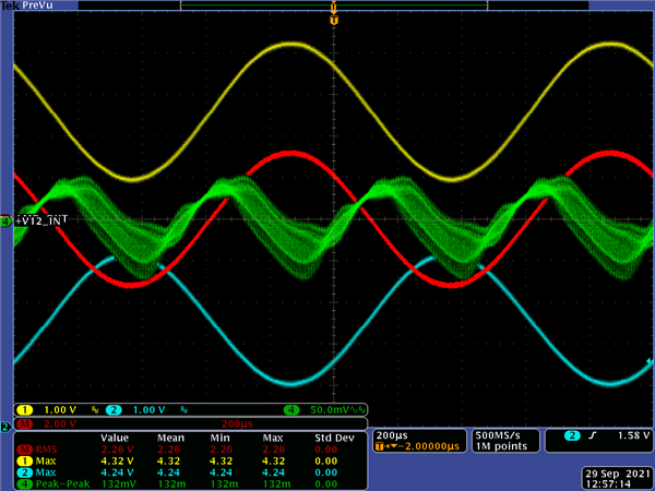
 

Test Result:

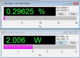
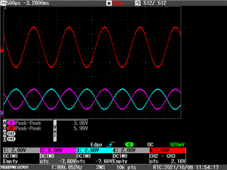
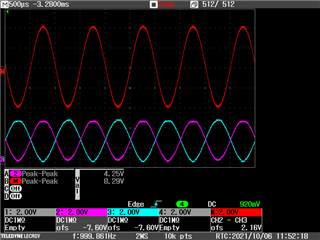
SPKR- (yellow) and SPKR+ (blue) get cut of although the output power is only about 2W according to the measurement.

And the +V5 supply voltage of the amplifier has almost 200mV ripple.
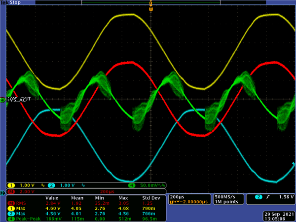
  

Second Test Setup:

The RC-low-pass filter was changed to a 30kHz filter with Rf = 100Ohm and Cf = 470nF
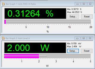
 

Second Test Result:

This time instead of measuring the +5V the mathematical function of the oscilloscope was used to calculate the difference between SPKR- and SPKR+. The RMS of the mathematical function was measured.

For some reason SPKR- and SPKR+ where not cut off although nothing except the RC-filter was changed compared to the last measurement.

Questions:

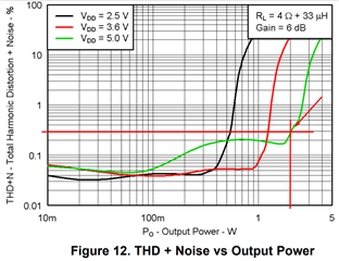
- What is the right way to measure the maximum output power of the TPA2011D1?

- What is the maximum allowed peak to peak level between the input pins IN+ and IN- of the amplifier?

- Do you see any issues with above shown schematic?

  • Hi Benjamin,

    I'll check on your questions and provide further comments early next week.

    Best regards,
    -Ivan Salazar
    Applications Engineer

  • Hi Ivan,

    It would be great if you could provide me an answer to my questions above today as this topic is quite urgent.

    Is it possible to arrange a meeting with you on teams or a similar chat app to speed things up?

    Thank you!

  • Benjamin,

    Some answers to your questions:

    • The measurement procedure is as described in data sheet Section 8.
    • You can input signals up to (VDD - 1.1V) V
    • I don't see a problem with the schematic, and your second capture may actually show the circuit is OK but perhaps not getting the measurement correctly.
      I think you're using a connection like the one displayed below, on the top diagram. I would suggest to use the connection from diagram on the bottom. Ideally you should connect the speaker directly at the output of the amplifier, even without ferrite+cap, but if not possible you can try this way.

    Best regards,
    -Ivan Salazar
    Applications Engineer

  • Hi Ivan,

    Thank you for your reply.

    I am measuring with the following setup which I think should be the same as the bottom one on your picture above:

    I tried using a 4Ohm speaker instead of the 4Ohm resistor I used before.

    With the speaker the output power I measure is even less than with the Resistor.

    We need an output power of 2W which should be not problem for the amplifier when supplied with 5V.

    But according to my measurements I can not reach 2W output power without the output sine getting cut off.

    To demonstrate this I changed R21 and R22 back to 130kOhm and R23 to 62kOhm to increase the gain.

    With this setup the input signal can be adjusted to see the impact on the output power.

    Yellow (SPKR+), blue (SPKR-), red (SPKR+ minus SPKR-), green (+V5 input ripple)

    The first measurement was done with the input signal set to 75% via windows:

    The output power is calculated with: square (RMS output voltage) / Load resistance = (2.26V)^2/4Ohm = 1,28W

    To get an output power of 2W a RMS output voltage of 2.83V is needed.

    Therefore I increased the input signal volume until the output voltage reached 2.83V (signal set to 85% via windows)

    With the input at 85% the output power is about 2W according to my calculation. But the sine is already cut of at this state.

    Please let me know why I am not able to reach an output power of 2W and still have a proper sine.

    As you can see I also measured the +V5 supply voltage ripple of the amplifier. Is a ripple of 120 to 170mV normal or does this suggest an issue?

    Is my calculation of the output power as mentioned above correct?

  • Hi Benjamin,

    Is there a chance you can try by replacing ferrites with 0-ohm resistors and removing C45/C46? I want to rule out the filters here.
    I'm looking for EVM on my side to replicate your test. Will keep you posted on any updates.

    Best regards,
    -Ivan Salazar
    Applications Engineer

  • Hi Ivan,

    I did the changes you suggested and measured the output signals an power again. There was only a very small increase from 2.71V to 2.73V RMS of the output signal. Over all I don't think this is the solution for our issue.

  • Hi Benjamin,

    I'm testing this on EVM and will share a test report with connections and results.
    Regarding the supply ripple you're seeing, what is your supply? Is it a battery, DC adapter or bench power supply? I'm testing with bench supply but can check some other cases if needed.

    Best regards,
    -Ivan Salazar
    Applications Engineer

  • Hi Ivan,

    The 5V supply voltage of the amplifier is sourced via the HD_Audio connector on our carrier board.

    The carrier board is supplied by a power supply PCB designed by us.

    A TI_TPS51125RGET on that PCB is generating the 5V.

  • Hi Benjamin,

    I completed test with EVM for 3 different loads:

    • 4Ohm
    • 8Ohm
    • 500Ohm

    For higher loads you should be able to reach close to VDD supply, lower loads would limit the voltage drive.
    Please check with different power supplies, and also try changing your decoupling capacitors: you're using 5V supply and 10uF/6.3V, ideally decoupling caps should be rated for 2 or 3 times the DC voltage it will bypass.

    Best regards,
    -Ivan Salazar
    Applications Engineer

  • Hi Ivan,

    Thank you for the test results.

    What RC-low-pass filter did you use for your measurements?

    If I see it correctly you also can't reach 2W output power with your 4Ohm setup. Or am I missing something?

    To have 2W output power the signal has to be about 8V peak to peak or 2.84V RMS.

    It also seems like your output signals already have quite some distortion. According to the Datasheet the distortion at 2W with 4Ohm load should be almost unrecognizable with only 0.3%

  • Benjamin,

    I just notice my load is not 4-ohm but 2-ohm. Please see below for 2-ohm and 4-ohm test, sorry for the confusion:

    • 2Ohm
    • 4Ohm

    As you mentioned, there is already some distortion (~0.3%) at the positive peak of the waveform.

    EDIT: I'm using AUX-0025 filter for this measurement: https://www.ap.com/download/aux-0025-0040-0100-data-sheet/?wpdmdl=7374

    Best regards,
    -Ivan Salazar
    Applications Engineer

  • Hi Ivan,

    Thank you for the update. The second measurement with the 4Ohm resistor helps a lot.

    I was not aware that 0.3% distortion is already that visible on SPKR- and PSKR+. I thought those spikes meen a lot more distotion.

    If it is possible it would be great if you could send me the last picture in a bettter resolusion as it is quite hard to see details on it at its current size.

    Thanks a lot for your support so far.

  • Benjamin,

    Not sure if resolution will be better, but here are the captures attached:

    SCRN.zip

    Best regards,
    -Ivan Salazar
    Applications Engineer

  • Hi Ivan,

    Thanks again for your support.

    With the results of your comparison measurements and the additional information on the distortion during the test this issue is resolved from my side.

    To improve the supply voltage stability we will change the 10uF/6.3V capacitor, to one with 2 or 3 times the DC voltage it will bypass.

    Best regards,

    Benjamin Weiß

  • Hi Benjamin,

    Thanks for getting back for closure. Let us know if anything else comes up, hopefully it is all good now.

    Best regards,
    -Ivan Salazar
    Applications Engineer