This thread has been locked.

If you have a related question, please click the "Ask a related question" button in the top right corner. The newly created question will be automatically linked to this question.

LM48511: Random pulses in Vboost making popping noise in the speaker.

Part Number: LM48511


I used this amplifier in another design with no problems.  I've copied it to a new design, keeping the same schematic, and artwork.

I have 3 proto PCBs now that all are making this popping sound.

I tried disconnecting the input caps from the previous stages, so the amp is isolated from other circuits driving it.  Still has the same noise.

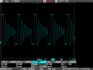
I looked at the switch pins 2,3 and the high frequency switching is stopping / starting.  This causes dips in the boost voltage. 

As soon as even a slight level of audio is at the input,  the popping goes away.

I also tried drawing 10 or so mA off  the boost output, but this has little effect.
I also tried paralleling some of the caps, in case of wrong value.  Made no difference.

I have the SD pin pulled up, SS/FF pin high.

Any ideas what else to look for?  

  • Hi David,

    The popping sound you mention is constant and periodical while the device is powered? Or only observable during power up or power down?
    Have you tried to disable and re-enable the boost by toggling SD_BOOST pin? Is it making any difference?

    Best regards,
    -Ivan Salazar
    Applications Engineer

  • Hi Ivan,

    The popping is kind of like crackling, but lower rate [frequency] than what I would normally think of as crackling.  It is not a turn on / off thump type thing.

    The boost SD pin was wired to the +5V supply, so I cut it free, and tested - When the boost SD is grounded, the popping stops.  Of course, the boost voltage drops.

  • Hi David,

    Thanks for the details. I understand you're using the same previous design but you didn't see this behavior before, correct? What could have changed from previous batch to this one? Is there any passives difference?

    Is there any chance you have one of the previous boards and potentially replace the IC? This to check if IC or Board follows the instability.

    Another idea for debugging I have is to AC couple the inputs to GND, also try higher Css and check if there is difference.

    I could try on EVM, but since this could be related to board or something else around the device I most likely won't have the same behavior.

    Best regards,
    -Ivan Salazar
    Applications Engineer

  • J-814 Rev 00 Schematic.pdf

    This is the schematic I have used, for both the PCB that works, and this new one with the instability.

    I think we have one of the older boards, so I'll get one of those.

    Getting the IC off is a challenge, since they have the big pad in the middle - it's a 2 person job.  Getting enough heat into the 4 layer PCB to that pad takes an iron with a big tip on the bottom while someone else uses the hot air wand for the pins.

    I have 3 boards that all work, except that they have this same instability.  I figure this means it's not a one bad part kind of thing.  I made no changes to the parts values we used, unless something was out of stock and had to make a substitution, but the main values would be the same.

    I tried grounding [all of these using a 4.7uF capacitor to block the DC] the input at the test point SpL, which actually makes the popping noticeably louder [6dB or so].  When I ground C76, no change.  When I ground C74, I get the increased level popping.

    When I put a 1uF cap across Css, the popping stops.  What size should I use?  OR just go up  100nF until I get a couple steps past it stopping?

  • Hi David,

    Thanks for the additional details.
    I'll take a look at your schematic and make some analysis on the Css cap solution. I'll come back with further details later today or early next week.

    Best regards,
    -Ivan Salazar
    Applications Engineer

  • Hi David,

    If you haven't already, I would go ahead with testing different capacitor values for Css, 1uF might be too high and increase the boost power up time considerably, although if that is not a problem it should be OK.

    Since this seems related to the boost, you could also try with the boost load capacitor, currently you have 100uF/10V, you may try with higher voltage rating for this capacitor.

    Best regards,
    -Ivan Salazar
    Applications Engineer

  • Since the Vboost is less than 10V, why is the 10V cap a question?

    I paralleled a 100uF tantaulm, it made the pulses more rounded / took out the sharpness of the slopes.

    I also seem to have been faked out by my initial test of paralleling the Css - today, it reduces the crackling, slows it, reduces the high frequency energy, but it's not gone.

    Thank you,

    Dave

  • Dave,

    As mentioned, 2 or 3 times the voltage is recommended, I understand boost is lower than 10V but it's still not 2 or 3 times, as mentioned.
    I got an EVM I can test by end of this week, although most likely I won't see the issue. It seems the charge cycle of the boost is not good thus causing the artifacts. You should check around the boost as that seems to be the source of the issue.

    If want to try something else, perhaps check if removing the load from the output is making a difference, and try different impedances. What is your load currently 4ohm or 8ohm? Is it a speaker or resistive load with inductor?
    You may try also removing the ferrites and see if it makes a difference.

    Best regards,
    -Ivan Salazar
    Applications Engineer

  • Ok, I missed the 2or 3 times part...  I removed the 10V cap, put in a 20V tantalum, which made no change.

    I ordered some new caps, rated at 25V to try.  100uF Tant, and some 47uF ceramics [figuring 2 parallel is close] There were no 100uF 25V ceramics in stock.

    The last tests I've been doing with no load.  I also had run it with an 8 ohm speaker.  With / without doesn't make much difference.

    I was thinking get rid of the ferrites, but with no load, they really shouldn't be able to do anything I would think.

  • Hi David,

    Thanks for further feedback. I'm discussing this with more people in the team for ideas, will let you know what comes up from that.

    I'm also thinking what could change in terms of PCB since that's the main change you mentioned, perhaps some inductance to GND connections?

    Best regards,
    -Ivan Salazar
    Applications Engineer

  • These are not the best prints, but for a start anyway...  The J-668 is the design that did not have this problem.

    amp layout J-668 Rev 03.pdf

    amp layout J-814 Rev 00.pdf

    The J-814 is the one with the popping.  


    Differences -

    The layout is rotated 180 degrees.

    The 668 version was powered from another PCB, not tied to any other wiring on the PCB.

    The 814 version is power off the board it is on.  I used a zero ohm resistor to tie the amp ground system to the PCB gnd at one point.

    Red is solder side, green is component side, aqua is GND plane.  The power plane isn't shown, since it is not wired to the amp.

  • Hi David,

    Let me take a look at these and give you further comments early next week.

    Best regards,
    -Ivan Salazar
    Applications Engineer

  • Hi Ivan,
    I got some 47uF 25V ceramic caps in, put 2 of them in parallel for the main boost cap.   Figured 2  would be close enough to the 100, since so many parts are out of stock these days...   Anyway, this made no noticeable difference with the noise. 
    Dave

  • Hi David,

    Since the amplifier was the only chip on the first design, I'd like to rule out everything else on the board for debugging. Is there a way you can only power LM amplifier without the rest of the circuit? I'm thinking of removing FB34 and connecting power directly from bench top supply on the amplifier side.

    Best regards,
    -Ivan Salazar
    Applications Engineer

  • Good idea.  I had isolated things somewhat earlier, but not quite as far.... So I just did this -  I disconnected the 2 input caps.  I disconnected the FB34 to isolate the power from the rest of the board.  I connected the lab supply to the amp GND pad, and the +5Vb pad - these are direct to the amp circuit only.  I still have the same result, the boost output is start / stopping, making the burbling noise.

  • Hi David,

    Thanks for feedback, unfortunately not identifying root cause yet.
    Let me check what else could be tested and I'll get back to you.

    Best regards,
    -Ivan Salazar
    Applications Engineer

  • Any other ideas on this?

  • Hi David,

    Next thing I could think is the sequence during power up. Would be worth checking what are the differences in terms of power and signal sequence including  VDD, SD_Boost, SoftStart.

    Best regards,
    -Ivan Salazar
    Applications Engineer

  • Here are some oscilloscope images of what is going on.

    This is the soft start pin.  2V / div the bottom points are at about 0V.

    Switch pin signal.  

    Boost test point.  Voltage varying between 6-8V.

    Sweep 10mS/div.  The incomplete sweeps are combination of the camera shutter and the randomness of the pulses.

    This is with a 470nF cap on the SS pin.  Going to 1uF masks the noise - it's still doing the same thing, just slower, so it doesn't make the noise as easy to hear.   The variations end up on the speaker output terminals, so the speaker makes noise.

    The input caps are lifted, so the other audio circuitry on the board is not connected to the amp.  I've looked over the layout, and I have not found any differences [comparing to the board I made that doesn't do this] that look meaningful yet. 

    Dave

  • Hi Dave,

    Thanks for the feedback and the captures, I'll double check how EVM is looking compared to this, will try to use different capacitors for comparison.

    Best regards,
    -Ivan Salazar
    Applications Engineer

  • I have found something.... Not sure what it means at this point.  I got one of the other PC boards from the earlier project.  It is doing the same thing as far as the boost voltage pulsing.  But I discovered that the variations don't show up as a signal to the speaker.  I also found that in this board, now that I have the input caps isolating the power amp from the circuits that feed it, there is no sound from the speaker, even though the pulsing is still going on.

    Should the Boost voltage be doing this jumping, as shown by the above scope traces?

    Dave

  • Additional - I have a speaker connected, input caps lifted.  V Boost is pulsing.  Speaker is quiet.   I have a test setup with a probe that is connected to a DVM, and a scope probe, and an audio amp input with a DC blocking cap.  When  I connect my test probe to one speaker lead [or the other] I can hear the noise from the test amp.  When I touch the probe to one of the inputs, I not only hear the noise in the test probe speaker, but in the speaker driven by the power amp.  The DC bias on the input is bobbling around with the pulsing.

    Dave

  • I suspect that we never heard the noise in our older board because the 2 inputs are driven by 2 identical opposite outputs, so the sum cancels, differential input style.

    The new board has only a single audio signal from a CODEC output, which is connected to 1 input, and the other input is driven by a unity gain inverting op amp stage, so the impedance is not the same, and also, this early testing I have not had the board with the CODEC plugged in, so that line is not driven.  But this still leaves me with the question about whether the V boost should be jumping around like it shows on the scope traces.

    Dave

  • I just noticed this from the data sheet - maybe the  boost regulator is running in discontinuous mode?  

    The LM48511 will limit its switch current based on peak current. With IP fixed, increasing L will increase the
    maximum amount of power available to the load. Conversely, using too little inductance may limit the amount of
    load current which can be drawn from the output. Best performance is usually obtained when the converter is
    operated in “continuous” mode at the load current range of interest, typically giving better load regulation and
    less output ripple. Continuous operation is defined as not allowing the inductor current to drop to zero during the
    cycle. Boost converters shift over to discontinuous operation if the load is reduced far enough, but a larger
    inductor stays continuous over a wider load current range.

    The noise seems to go away when I put big enough audio through the amp, although it also makes it harder to hear the noise.

    Dave


  • This is the switch pin with the sweep set to 1uS/div.

    Dave

  • Hi Dave,

    I think that last capture makes sense. I see something similar on the EVM, it can change depending of the loading (reducing load impedance and/or playing sine tone):

    These captures are from SW pin, I don't see any significant variation at the output of the Diode.

    That thing you mentioned about differential vs pseudodifferential using inverter at the input could also be related. Perhaps there is some oscillatory artifact at the input caused by the inverter, out of phase or similar, then causing the boost to misbehave.
    You may need to reduce the effects both from boost capacitance, as observed before, and the input signal.

    Best regards,
    -Ivan Salazar
    Applications Engineer

  • Well, the inverter stage is isolated at this time, since the 2 input caps are lifted.   The other board, the amp inputs are open for these tests.  It was made to connect to another board that has a balance driver driving them, so no common mode problem making the noise show up as an input to only one side.

     Your waves are clean and stable.  On mine, the boost system seems to be stopping and restarting with a large random component.  I also tried drawing 40 and 80 mA from the boost pin - which made the frequency of the stop / start increase.

    I am setting up my current probe to see what the inductor current is doing...

    Dave

  • Hi Dave,

    Can you please remind me of the boost capacitors you're using? And if you tried different ones?
    EVM is using Tant cap at the output of the boost, I'll check if using Ceramic ones makes a big difference in the stability or something else.

    Best regards,
    -Ivan Salazar
    Applications Engineer

  • The original / as built is a 100uF 10V Ceramic.  During these tests, we tried a tantalum, and I now have 2) 47uF 25V caps paralleled for the boost cap.   Changing the caps has had no effect in the start / stopping.

  • Thanks, I'll check on some similar/same cases with EVM.

    Regarding the input, I think you mentioned the input AC coupling caps are open, correct? But have you tried to connect them to GND? I mean AC couple to GND the inputs. Perhaps some noise is coupling to the input and floating the caps is not really getting rid of that coupling.

    Best regards,
    -Ivan Salazar
    Applications Engineer