This thread has been locked.

If you have a related question, please click the "Ask a related question" button in the top right corner. The newly created question will be automatically linked to this question.

TLV320AIC3120: Inquiry about MCLK

Part Number: TLV320AIC3120

Hello Expert,

Our customer is under design w/ this device.

Their board is configured two board which is processor b'd and audio codec b'd.

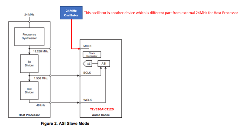
This audio codec can't receive MCLK from processor b'd.

So they have to use another clock source from another oscillator which is different from oscillator of process.

Below is their block diagram to use it.

Is there no problem? Can they use it?
Best Regards,

Michael

  • If you want to combine, write it at later stage.

    I will take a look again late next week.

    Regards.

  • Hi Peter,

    We are waiting your feedback.

    Pls check and let us know.

    Regards,

    Michael

  • Give me couple more days, I'm waiting for the team to provide feedback if anything else we can do.

  • Try changing the RC filter with a LC filter, start with L=33uH and C=660nF and see if that's ok for their system

    You can tune that further by increasing the cap value if needed.

  • Hi Peter,

    Is there any improvement?

    Could you please let me know the captured waveform before and after applying LC filter?

    I have to check it first and I need captured waveform in condition of span (40us/div, 200mV/div) of oscilloscope.

    Pls, understand my request.

    Regards,

    Michael

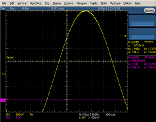
  • With RC:

    with LC (33uH, 660nF):

    with LC (33uH, 853nF):

  • Hi Peter,

    Could you please do me a favor?

    This register setting is what you sent to me before.

    Could you please give a register setting to me for 16khz sampling rate?

    # page 0 is selected 
    w 30 00 00
    # s/w reset
    > 01
    # Program Clock Settings
    # (a) Program PLL clock dividers P,J,D,R (if PLL is necessary)
    #
    # PLL_clkin = MCLK = 12.288MHz, codec_clkin = PLL_CLK,
    w 30 04 03
    # J=8, D=0000
    w 30 06 08
    w 30 07 00
    w 30 08 00
    #
    # (b) Power up PLL (if PLL is necessary and P & R value)
    # P=1, R=1,
    w 30 05 91
    # NDAC is powered up and set to 2
    w 30 0B 82
    # MDAC is powered up and set to 8
    w 30 0C 88
    # DOSR = 768, DOSR(9:8) = 11, DOSR(7:0) = 00
    w 30 0D 03 00
    #
    # (f) Program I2S word length as required (16, 20, 24, 32 bits)
    #
    # mode is i2s, wordlength is 16, slave mode (default)
    w 30 1B 00
    # select DAC DSP Processing Block PRB_P4
    w 30 3C 04
    w 30 00 08
    w 30 01 00
    w 30 00 00
    #
    # page 1 is selected
    w 30 00 01
    # Program common-mode voltage (defalut = 1.35 V)
    #
    w 30 1F 04
    # De-pop, Power on = 800 ms, Step time = 4 ms
    w 30 21 4e
    #
    # Program routing of DAC output to the output amplifier (headphone/lineout or speaker)
    #
    # DAC routed to HPOUT
    w 30 23 40
    #
    # Unmute and set gain of output driver
    #
    # Unmute HPOUT, set gain = 0 db
    w 30 28 06
    #
    # Power up output drivers
    #
    # HPOUT powered up
    w 30 1F 82
    # Enable HPOUT output analog volume, set = 0 dB
    w 30 24 80
    # 5. Power up DAC
    # (a) Set register page to 0
    #
    w 30 00 00
    # Power up DAC channels and set digital gain
    #
    # Powerup DAC (soft step enabled)
    w 30 3F 94
    #
    # DAC gain = 0 dB
    w 30 41 00
    # (c) Unmute digital volume control and set gain
    #
    # Unmute DAC
    w 30 40 00

    Best regards,

    Michael

  • Change DOSR from 768 to 384 in register 0x0D with this and keep the rest the same:

    w 30 0D 01 80