This thread has been locked.

If you have a related question, please click the "Ask a related question" button in the top right corner. The newly created question will be automatically linked to this question.

PCM9211: Create an SPDIF to i2s to SPDIF converter

Part Number: PCM9211
Other Parts Discussed in Thread: DIX9211

Hi!

A while ago I designed a soundbar distribution board that uses the WM8804, which is an audio transceiver that I set up to convert i2s to SPDIF.

This has worked great, but for some reason, certain soundbars don't like the outputted SPDIF signal, and the sound gets all weird. It's almost like the soundbar tries to convert the signal into a surround sound or something.

However, these soundbars do accept the PCM9211 SPDIF signal, so I'll try to use this.

BTW I've done quite a lot of research, and there is simply no way to make the soundbars accept the WM8804 signal. I've tried various settings in both hardware and software mode, but no luck.

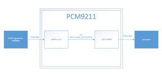
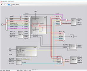
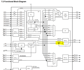
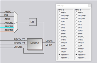
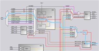
Anyways, since the soundbar distribution system is already sold, I have to design a board that takes the existing SPDI signal as an input, converts it to i2s, and then converts it back to SPDIF again. The PCM/DIX9211 is indeed a transceiver, and by looking at the CodecControl interface, it looks like it might work. I do have a PCM9211EVM board to play around with, but I haven't succeeded yet.

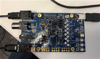
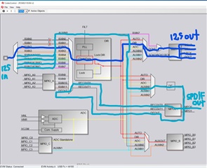
I've externally routed all the i2s outputs to the i2s inputs on the board (signal on connector P7 connected to header W11), and I've desoldered U8 (74LCV244) and connected the input optical signal directly to RXIN2.

I can verify that I have a correctly decoded i2s signal on the i2s outputs, and I also have a valid SPDIF signal on the output. Still, there is no sound, so there is clearly something wrong.

How can I turn the PCM9211 into a SPDIF -> I2S -> SPDIF converter?

Thanks!

  • Hello,

    Sorry for the late response on this, but give me time to review your design and give feedback by the end of the week.

    Best Regards,

    LPA Apps Engineer

  • No worries, thanks for reaching out!

    Waiting for your reply then.

  • Hans,

    I think you can do a loop back configuration where the serial data output pin is externally connected to the serial data input pin. This should route SPDIF in -> I2S out -> I2S in -> SPDIF out.

    Brian

  • This is currently what I've done. It's not so easy to see in the picture, but the i2s signals are wired from the P7 connector (I2S out) to W11 (pin 3 to 6, i2s input). I can verify that I have a valid i2s signal on these lines (by using a Quantum Data SPDIF generator), but I can't make the i2s to SPDIF part work.

  • Hello,

    Sorry for late response but could you point out what output is not working in the right most image given the process you described?

  • I'm getting something that looks like a valid SPDIF signal on the output connector, but there is no sound when connected to an SPDIF compatible receiver.

    Since I'm using the evaluation board, the SPDIF transmitter is connected MPO0 or MPO1. I've tried both, but still no sound. As mentioned earlier, the SPDIF to i2s parts seems to work fine

  • Hello,

    Since you are converting back and forth aren't you trying to use the same multiplexer and data/clock systems at the same time when you loop back in with the I2s. Or is this something that you already considered and ruled out as the problem?

    Best Regards,

    Carson

  • I'm not sure I understand your question, but I'll try to answer as well as I can. From the looks of the schematic diagram in CodecControl, it looks like the multiplexer that handles all the external inputs has a "second multiplexer" that can route signals to RECOUT0 and RECOUT1. This is what I'm trying to use.
    To better illustrate the signal flow I try to achieve, I've attached a screenshot where I've drawn in the signal path (that's obviously not working). I can confirm that the dark blue route is working, and I can confirm that there is an SPDIF signal on the MP0 output, just not the one that comes from the i2s input.

  • Okay thanks for the illustration, I will look this over and get feedback to you.

  • Yeah it would all seem to be okay except that first big multiplexer is being used twice in your signal path which might be the core of the issue because I do not see why else there would be a problem

    Looking in datasheet the block diagram shows you dont even need to go back through that multiplexer 

    Is it possible on your side just to program the MPO0/1 ports to directly take in the DIT output instead of RECOUT?

    Best Regards,

    Carson

    LPA applications Engineer

  • It's theoretically possible for me to connect MP00/1 to DIT directly, but I can't figure out how it's done! These are the options I get in CodecControl when I click the MPO0/1 box, but none of these connects the DITOUT signal to MPO0/1 as far as I can understand. I've also looked in the datasheet, but can't really figure out how it's done.

    Is there any way to verify that the I2S signal connected to RXIN4-RXIN7 is actually "accepted" and present on the internal AUXIN0 line?

    EDIT:

    I can verify that I have a valid AUXIN0 signal by routing it out of the MPIO_B port and measuring the signals with an oscilloscope (P6 connector on the EVM board). When I change the sample rate on the SPDIF signal generator, I can see that MCLK and LRCLK change, which means that this signal is in fact generated from the received SPDIF stream.

    The only question now is how to get the AUXIN0 signal out of the MPO0/1 port(s). I try manually tweaking the "RECOUT0/1 Output Biphase Source Settings Register" (register 35h and 36h), but no success.

  • Hello,

    I believe TXOUT would be equivalent of the output of the DIT, have you tried that selection?

    Best Regards,

    Carson

  • I think I've found a solution. It's different from what I initially thought I was going to do, but it does work for what I'm trying to do. First, there is a bug in CodecControl. The register that controls the mux before the DIT (Register 60h) isn't properly set, it only sets the first four bits, but all 8. By manually controlling this register I was able to get it to work.

    However, I couldn't get the AUXIN0 or 1 to work even though I wrote 0x33 or 0x44 to the register. However, I was able to get it to convert the SPDIF signal internally by connecting the mux to AUTO (0x00) or DIR (0x11).

    Why AUXIN0 or AUXIN1 didn't work is a mystery though. I did wire a valid I2S signal from the I2S output of the PCM9211 to

     AUXIN0 and MPIO_C/AUXIN1, but no success there...

    The following program flow works for what I'm trying to do, so I'm all happy!