This thread has been locked.

If you have a related question, please click the "Ask a related question" button in the top right corner. The newly created question will be automatically linked to this question.

PCM9211EVM-U: Clock level issue

Part Number: PCM9211EVM-U
Other Parts Discussed in Thread: PCM9211,

Hi TI experts,

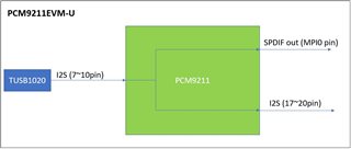
Customers are testing DIX output with PCM9211EVM. they has setting example code provided by TI. (using PCM9211 GUI)

First step : set to PCM9211_init.txt

Second step : set to PC Record via TAS1020 through MPIOC in DIT output.txt 

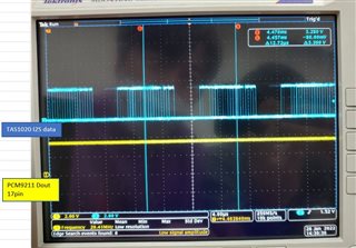
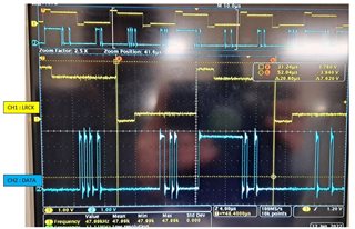
When set as above, the I2S clock waveform output from TAS1020 is abnormal.

Can you test this problem using your EVM?

Please review what caused it.

Thank you.

  • Hello Downey,

    Are they using our released EVM and measuring the clock on it? if yes, is the I2S going through the level shifter and PCM correct? I don't have the EVM to verify their observation but still we may be able to  see what might be the issue.

    Regards,

    Arash 

  • Hi Arash,

    Yes, they use PCM9211EVM-U. we are checking waveform TP7(WCLK) of PCM9211EVM.

    Please refer user guide 23page.

    https://www.ti.com/lit/ug/sbau174/sbau174.pdf

    When connect EVM to PC and don't open PCM9211 GUI, I2S clock is normal. 

    If we open the GUI and set the TI example code, the I2S clock becomes abnormal.

    Thank you.

  • Thanks Downey, Seems to me that the WCLK from Buffer ( U7) and TAS1020 (at TP7) might be fighting with each other. Could you ask them to make sure this is not the case? On hardware,  they can disconnect the buffer output from that of TP7  and  use the same code/GUI. If they don't want to touch the EVM they can  modify the code so these I2S are not competing with each other..

    Kind Regards,

    Arash

  • Hi Arash,

    Thank you. I will share your advice with the customer.

    Can you create example script for customer?

    Customer require condition is below block.

    PCM9211 :

    I2S input : MPIO_C0~3(from TUSB1020)

    I2S output : 17~20pin (bypass from TUSB1020)

    SPDIF out : MPI0 (I2S to SPDIF)

    Thank you.

    Downey Kim.

  • Downey, lets wait for them and see if they can modify their script so both units are not in master mode and we go from there. TAS1020 should be Master and PCM9211 slave. If they can not figure it out, probably I will be able to put some time next week to work on a script.

    Regards,

    Arash

  • Hi Arash,

    Customers can't set it as they want. we need your support. 

    Can you create example script?

    Thank you.

  • Hi Downey,

    I have added this to my list of "things to do" and I will work on it next week. If I can, I will work on this week but it is unlikely. Meanwhile please send me the script that the customer is using now and has issue with it ( just to make sure I start from where they are, in case they made any modification to their original script.)

    Regards,

    Arash

  • Hi Arash,

    They are first reviewing the PCM9211EVM by entering an example script.

    The audio input from the PC is not output to the SPDIF of the PCM9211EVM.

    #**************************************
    #this script is for PC USB playback to TAS1020--->PCM9210 MPIOC-->AUXIN1 to DIT-->MPO0/1 SPDIF output
    #MPIOC which is connect with TAS1020's BCLK WCLK, configured as AUXIN1
    #So
    #1, you should configred MPIOC as AUXIN1.
    #2, Configure DIT settings.
    #3, Chose AUXIN1 as DIT source
    #4, Chose DIT out as MPO output
    
    
    #System RST Control
    #w 80 40 00
    w 80 40 33
    w 80 40 C0
    
    #XTI Source, Clock (SCK/BCK/LRCK) Frequency Setting
    w 80 31 1A
    w 80 33 22
    #w 80 20 00
    #w 80 24 00
    #w 80 26 01
    
    #XTI Source, Secondary Bit/LR Clock (SBCK/SLRCK) Frequency Setting
    #w 80 33 22
    
    #*********************************************************
    #-------------------------------Start DIR settings---------------------------------------
    #REG. 60h DIT System Clock Source Select, DIT Bit clock, LR Clock, Data Source Select, here chose AUXIN1
    w 80 60 44
    
    #REG. 60h DIT System Clock Control(here is 256 Fs), DIT DSD input enable(here is disable), DIT Audio I/F Format Setting(here is I2S)
    w 80 61 10
    
    #REG. 62h DIT Output Audio Data Mute Control(no mute), DIT Output Validity Flag Control(Valid)
    w 80 62 00
    #***********************************************************
    #------------------------------------ End DIR settings------------------------------------------
    
    #----------------------------
    #REG. 78h, MPO1, MPO0 Function Assign Setting. MPIO0 1 both output DIT
    w 80 78 DD
    #--------------------------
    
    
    #------------MPIOC-->AUXIN1
    w 80 6E 0F
    w 80 6F 40
    #-------------end----------------

    Using script file name is below.

    PC Record via TAS1020 through MPIOC in DIT output.txt

    can you review this problem?

    Thank you.

  • sure, I will be out of office for couple of days, so i work on it before I leave . I should have some results or observations  sometimes tomorrow.

    Regards,

    Arash

  • Hi Arash,

    I found document for PCM9211EVM application note.

    https://www.ti.com/lit/an/sbaa179/sbaa179.pdf

    There is the same signal path as the function requested by the customer in 6page,

    We did set GUI as in the Application note.

    We confirmed that the SPDIF output was normal.

    However, it is different from the I2S output(17~20pin) being input to the MPIOC(from TUSB1020).

    Please check this script.

    w 80 42 19
    w 80 42 11
    w 80 42 10
    w 80 46 0f
    w 80 46 10
    w 80 46 13
    w 80 46 1e
    w 80 46 25
    w 80 46 2c
    w 80 46 31
    w 80 46 38
    w 80 46 41
    w 80 46 48
    w 80 46 50
    w 80 46 57
    w 80 46 5f
    w 80 46 64
    w 80 46 69
    w 80 46 6e
    w 80 46 74
    w 80 46 79
    w 80 46 7f
    w 80 46 83
    w 80 46 88
    w 80 46 8e
    w 80 46 93
    w 80 46 98
    w 80 46 9d
    w 80 46 a3
    w 80 46 a5
    w 80 46 a9
    w 80 46 ad
    w 80 46 b2
    w 80 46 b4
    w 80 46 b5
    w 80 46 b9
    w 80 46 bc
    w 80 46 bd
    w 80 46 be
    w 80 46 c1
    w 80 46 c2
    w 80 46 c3
    w 80 46 c4
    w 80 46 c6
    w 80 46 c7
    w 80 46 c8
    w 80 46 c9
    w 80 46 ca
    w 80 46 cb
    w 80 46 cd
    w 80 46 ce
    w 80 46 cf
    w 80 46 d0
    w 80 46 d1
    w 80 46 d2
    w 80 46 d3
    w 80 46 d4
    w 80 46 d5
    w 80 46 d6
    w 80 46 d7
    w 80 46 d8
    w 80 46 d9
    w 80 46 d8
    w 80 46 d7
    w 80 46 d6
    w 80 46 d7
    w 80 46 d8
    w 80 46 d9
    w 80 46 d8
    w 80 46 d9
    w 80 46 d8
    w 80 46 d7
    w 80 46 d7
    w 80 46 d7
    w 80 47 0f
    w 80 47 11
    w 80 47 14
    w 80 47 17
    w 80 47 1c
    w 80 47 22
    w 80 47 27
    w 80 47 2d
    w 80 47 33
    w 80 47 38
    w 80 47 3e
    w 80 47 45
    w 80 47 4b
    w 80 47 52
    w 80 47 5a
    w 80 47 61
    w 80 47 66
    w 80 47 6b
    w 80 47 70
    w 80 47 75
    w 80 47 7a
    w 80 47 7f
    w 80 47 83
    w 80 47 87
    w 80 47 89
    w 80 47 8b
    w 80 47 8e
    w 80 47 90
    w 80 47 94
    w 80 47 97
    w 80 47 9c
    w 80 47 9f
    w 80 47 a3
    w 80 47 a8
    w 80 47 aa
    w 80 47 ae
    w 80 47 b2
    w 80 47 b8
    w 80 47 ba
    w 80 47 bd
    w 80 47 bf
    w 80 47 c0
    w 80 47 c2
    w 80 47 c4
    w 80 47 c5
    w 80 47 c6
    w 80 47 c8
    w 80 47 c9
    w 80 47 cb
    w 80 47 cc
    w 80 47 ce
    w 80 47 cf
    w 80 47 d0
    w 80 47 d1
    w 80 47 d2
    w 80 47 d3
    w 80 47 d4
    w 80 47 d5
    w 80 47 d6
    w 80 47 d7
    w 80 47 d8
    w 80 47 d7
    w 80 47 d8
    w 80 47 d7
    w 80 47 d6
    w 80 47 d7
    w 80 47 d8
    w 80 47 d9
    w 80 47 d8
    w 80 47 d7
    w 80 47 d6
    w 80 47 d7
    w 80 47 d8
    w 80 47 d9
    w 80 47 d8
    w 80 47 d7
    w 80 47 d7
    w 80 47 d7
    w 80 34 80 e0 bc
    w 80 60 a4
    w 80 6b 04 b4
    w 80 6b 10
    w 80 6b 44 b4
    

    Thank you.

  • Hi Downey,

    I looked in to the scripts and I did not find any issue with them. I acquired 2 new EVMs  and I was able to duplicate the issue you have reported. I was constantly monitoring TP7 and pin5 of  P7 ( which is LRCLK of PCM4911.) Once the gui is opened, there is always LRCLK  present on that pin (pin5)  and of course it has contention with WCLK via U7. This has been clear from beginning that it is a case of signal contention, where WCLK is coming from  both TAS and PCM device.  You can verify this by removing the jumper W9 and you will have a clean clk on WCLK.  

    I tried to force the PCM's clk OFF or thought may be by forcing it to slave mode can help , but seems no matter what, we can not remove the LRclk for PCM4911 . You can shut down the whole clk  by writing f3 to  regitry 40  or switch to AUX clks to get clks from outside (by writing 44 to registry6B)  but it seems we can not simply make the PCM clks slave.

    So both your script and hardware are working okay and have no  issue. I believe  the issue you see,  should have no effect , since  this is a clk signal and its edges is the critical part and as long as the level is within the max/min of  signal level it should not be an issue.

    Regards,

    Arash

  • Hi Arash,

    Thanks for your support.

    I deleted the duplicate command.

    #System RST Control
    #w 80 40 00
    w 80 40 33
    w 80 40 C0
    
    w 80 42 19
    w 80 42 11
    w 80 42 10
    
    w 80 46 d7
    
    w 80 47 d7
    w 80 34 80 e0 bc
    w 80 60 44
    
    w 80 6b 44 
    #w 80 6b 14


    PC -> TUSB1020 -> PCM9211 optical out : this path is ok. we checked operation.

    But I2S DOUT of PCM9211 is not operated. (PC -> TUSB1020 -> PCM9211 I2S)

    Clock of PCM9211 I2S main output is ok. (SCK, BCK, LRCK). please refer waveform below.

    DOUT of PCM9211 is only high. please refer waveform below.

    Could you review this problem?

    Thank you.

  • I was out of office and I try to  take a look at it this week as I go through the list of my "to do". 

    Regards,

    Arash

  • Just wanted to let you know due to weather and road  conditions there will be some  delays but I will take a look at it on the bench next week.

    Regards,

    Arash

  • Hi Arash,

    We still haven't solved the problem. so we need your help!

    Thank you.

  • sure Downey, I will take a look at it, I just have few urgent task on my plate that I need to take care of them first. 

    Regards,

    Arash

  • Hello Downy I looked at the scripts  in details and found few things that I could not follow why they did it , of course I amnot saying that is the reason for what they see.

    #System RST Control

    #w 80 40 00

    w 80 40 33

    w 80 40 C0

    w 80 42 19

     w 80 42 11

    w 80 42 10

    w 80 46 d7

    w 80 47 d7

    w 80 34 80       ( 1000 0000)  b7=1 power down for RXIN0 coaxamp ( Please refer to note in DS)

    w 80 35  e0

    w 80 36  bc      (1011  1100   b4=1 mutes MPO1, b4= 0 is the default)

    w 80 60 44

    w 80 6b 44

    #w 80 6b 14

    The first thing is they  write in the same  register consecutively several times  (for example they right on registry 42 several times, only the last code will be effective , if they had other lines in between I would guess , may be they were setting it up for other registers first and then right the final code )

    In register 36, bit 4 mutes MPO1, is it what they want to do?

    In register 34 they write 80  , bit7 =1 but the notes mentions RX0DIS or RX1DIS must be set to 0, even when an S/PDIF, TTL, or OPTICAL input is provided into RXIN0 or RXIN1, without use of the built-in COAX amplifier. 

    Having said that, I couldn't figure out if  any of these could possibly put the output at  high all the time. I hope they can use this to make some modification to see if any of them makes a difference.

    Regards,

    Arash