This thread has been locked.

If you have a related question, please click the "Ask a related question" button in the top right corner. The newly created question will be automatically linked to this question.

TAS2553: Very low audio output

Part Number: TAS2553
Other Parts Discussed in Thread: TAS2552

Hi Team,

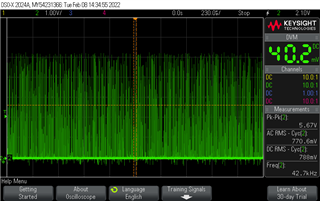
Recently we have replaced our old audio chip with TAS2553. But I couldn't get the desired audio output in the speaker as an earlier chip. I am getting very very low audio in the speaker out. 

I have read and verified all the configuration registers. 

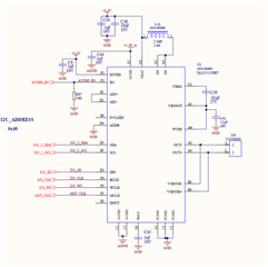
1 ) I2S digital Input,

2)  I2S WCLK configured as 22.05 khz

3) I have measured the frequency as BCLK -> 705 khz I2S_MCLK -> 5.6 MHZ

4) I am trying to play a 22ksps/48K sps audio file. I have switched the I2S frequency to 48K when playing the 48Ksps file.

I have configured as below,

uint8_t Device_config1_Array[2] ={TAS2553_CFR1,(CFR0_SWS_SHUTDOWN)};


uint8_t Device_config2_Array[2] ={TAS2553_CFR2,(CFR2_CLASSD_EN|CFR2_BOOST_EN|CFR2_IVSENSE_EN|CFR2_RESERVED_CFG)};//Reserved. MUST BE WRITTEN TO ZERO DURING 


uint8_t Device_config3_Array[2] ={TAS2553_CFR3, (CFR3_PDM_IN_SEL|CFR3_DIN_SOURCE_AVG|CFR3_I2S_OUT_SEL|CFR3_WCLK_22KHZ)};


uint8_t Serial_Interface_CTRL_Array[2] ={TAS2553_SERIAL, (SERIAL_WORD_16 | SERIAL_DATA_I2S|SERIAL_CLKPERFRAME_32)};


uint8_t Level_ctrlreg_Array[2]                ={TAS2553_LEVEL_CTRL, 0xA9};//Write to 0xA9 during initialization. See Initialization.


uint8_t PGA_Gain_Array[2] ={TAS2553_PGA_GAIN, PGA_GAIN_24db };//PGA_GAIN_0db


uint8_t Edge_Rate_CTRL_Array[2] ={TAS2553_CLASSD_RATE,(CLASSD_EDGE_CTRL_14ns)};


uint8_t Boost_Autopass_CTRL_Array[2] ={TAS2553_BOOST_AUTOPASS,(CLASSD_EDGE_CTRL_50ns)};


uint8_t Hystime_Lmtrate_Array[2] ={TAS2553_HYST_LIMIT,0x20};


uint8_t PLL_CtrlReg1_Array[2] ={TAS2553_PLL_REG1,(0x08 &TAS2553_PLL_J_MASK )}; //J = 8;


uint8_t PLL_CtrlReg2_Array[2] ={TAS2553_PLL_REG2,TAS2553_PLL_D_UPPER(0x1e)} ; // PLL set, uppder D =0


uint8_t PLL_CtrlReg3_Array[2] ={TAS2553_PLL_REG3,TAS2553_PLL_D_LOWER(0x5b)} ; // PLL set, Lower D =1

Kindly help me to fix the audio. 

  • My audio output for old IC and new TAS 2553 IC,

  • Hi Parama,

    I'll double check your configuration on my side and provide further comments.
    You mentioned to replace an old audio chip, was that a different part number? Were you using the same clock settings with the old part?

    Best regards,
    -Ivan Salazar
    Applications Engineer

  • Hi Ivan,

    The old IC is a different manufacturer(Cirrus logic). They were using FLL method. We have configured the FLL frequency as 75.898 Mhz and class AB amplifier. Now I calculated and configured the J.D and P values to get the 75.898 MHZ according to the TI datasheet. My output audio frequency is still very high around 42.7 Khz. 

    Thanks,

    Param.

  • I couldn't see any change in the output frequency in the out+ & out- waveforms. I changed clock sources as MCLK,BCLK, Internal OSC) and modified J,D,P values, but no variation in the output frequency level. Disappointed

  • Hi Parama,

    I'm trying a similar set of clocks on my side, I see distortion issues at higher frequencies most likely due to incorrect PLL configuration.

    You should calculate the PLL settings based on data sheet description: https://www.ti.com/lit/ds/symlink/tas2553.pdf#page=16&zoom=100,0,316

    Perhaps it's better to use MCLK as PLL source instead of BCLK, so that PLL_D can be used without compromising the conditions at the bottom of page 16 from data sheet.

    Best regards,
    -Ivan Salazar
    Applications Engineer

  • Hi,

    I am using MCLk as the source, since I write the value 0x01 at startup (SWS)  in the configuration register 1 and 0x00 at the end of configuration. I am not using bclk as the source.

  • Hi Parama,

    It is not clear to me where in the script MCLK is configured as PLL input, but I'll plan to do further testing based on MCLK. I'm currently working on several projects at this time so I may get some feedback early next week.

    Best regards,
    -Ivan Salazar
    Applications Engineer

  • Hi Parama,

    Can you run a sweep test and record the output level over time?
    The test results observed on my side show in-band cutoff and reflections at higher frequencies, I wonder if the symptom you mention is related to the same.

    Best regards,
    -Ivan Salazar
    Applications Engineer

  • Hi Ivan,

    Sorry for the late reply since I was busy with the project release. I fixed the problem by using BCLK as the source and the following configuration sequence. Luckily I saw the config detail in the TAS2552 development board software GUI. 

    uint8_t Device_config1_Array[2]        ={TAS2553_CFR1,(CFR0_SWS_SHUTDOWN |CFR0_PLL_BCLK)}; //MCLK
    uint8_t Device_Status_Array[2]         ={TAS2553_STATUS,0x20};
    uint8_t Device_config2_Array[2]        ={TAS2553_CFR2,(CFR2_CLASSD_EN|CFR2_BOOST_EN|CFR2_PLL_EN|CFR2_IVSENSE_EN /*|CFR2_APT_EN*/)};//Reserved. MUST BE WRITTEN TO ZERO DURING CONFIGURATION SEQUENCE as shown in Initialization.
    uint8_t Device_config3_Array[2]        ={TAS2553_CFR3, (CFR3_DIN_SOURCE_AVG |CFR3_I2S_OUT_SEL|CFR3_WCLK_22KHZ)}; 
    uint8_t Serial_Interface_CTRL_Array[2] ={TAS2553_SERIAL, (SERIAL_WORD_16 | SERIAL_DATA_I2S|SERIAL_CLKPERFRAME_32)}; 
    uint8_t Level_ctrlreg_Array[2]         ={TAS2553_LEVEL_CTRL, 0xA9};//Write to 0xA9 during initialization. See Initialization.
    uint8_t PGA_Gain_Array[2]              ={TAS2553_PGA_GAIN, PGA_GAIN_10db };//PGA_GAIN_0db
    uint8_t Edge_Rate_CTRL_Array[2]        ={TAS2553_CLASSD_RATE,(CLASSD_EDGE_CTRL_14ns)}; 
    uint8_t Boost_Autopass_CTRL_Array[2]   ={TAS2553_BOOST_AUTOPASS,(BOOST_APT_THRESH_V0pot2)};
    uint8_t Hystime_Lmtrate_Array[2]       ={TAS2553_HYST_LIMIT,0x20};
    uint8_t PLL_CtrlReg1_Array[2]          ={TAS2553_PLL_REG1,(0x20 &TAS2553_PLL_J_MASK)};  // 24.5760 MHz = (0.5 *J.D*PLLCLK)/2p
    uint8_t PLL_CtrlReg2_Array[2]          ={TAS2553_PLL_REG2,TAS2553_PLL_D_UPPER(0x0000)} ; // PLL set, uppder D =0
    uint8_t PLL_CtrlReg3_Array[2]          ={TAS2553_PLL_REG3,TAS2553_PLL_D_LOWER(0x0000)} ; // PLL set, Lower D =1 
    
      HAL_I2C_Master_Transmit(&hi2c2, ADDRESS_AUDIO_DEVICE, Device_config1_Array, TxCnt, Timeout);
      HAL_I2C_Master_Transmit(&hi2c2, ADDRESS_AUDIO_DEVICE, Device_config2_Array, TxCnt, Timeout);
      HAL_I2C_Master_Transmit(&hi2c2, ADDRESS_AUDIO_DEVICE, Device_config3_Array, TxCnt, Timeout);
      HAL_I2C_Master_Transmit(&hi2c2, ADDRESS_AUDIO_DEVICE, Serial_Interface_CTRL_Array, TxCnt, Timeout);
      HAL_I2C_Master_Transmit(&hi2c2, ADDRESS_AUDIO_DEVICE, PLL_CtrlReg1_Array, TxCnt, Timeout);
      HAL_I2C_Master_Transmit(&hi2c2, ADDRESS_AUDIO_DEVICE, PGA_Gain_Array, TxCnt, Timeout);
      
      Device_config1_Array[1]                  = 0x00 | CFR0_PLL_BCLK;
      HAL_I2C_Master_Transmit(&hi2c2, ADDRESS_AUDIO_DEVICE, Device_config1_Array, TxCnt, Timeout); 
    

  • But I wonder it didn't follow the sequences as mentioned in the datasheet in the Initialization section.

  • Hi Parama,

    Good to know it is working for you now. Thanks for sharing this information.
    I'll compare the init sequence from GUI to the data sheet and request any changes needed on the documentation.

    Best regards,
    -Ivan Salazar
    Applications Engineer