This thread has been locked.

If you have a related question, please click the "Ask a related question" button in the top right corner. The newly created question will be automatically linked to this question.

LM48580: Turn on pop up click

Part Number: LM48580

Hello,

we are working on integrating a MEMS speaker into a product.
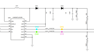
The LM48580 amplifier is used in this application to drive a MEMS speaker.

The MEMS speaker requires a DC offset on the driving signal. For this purpose we use the Vbst from the LM48580 coupled into the OUT+ path via a 10kOhm resistor and decoupled from the output (OUT+) via a 2.2µF DC block capacitor.

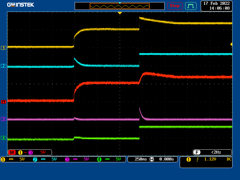
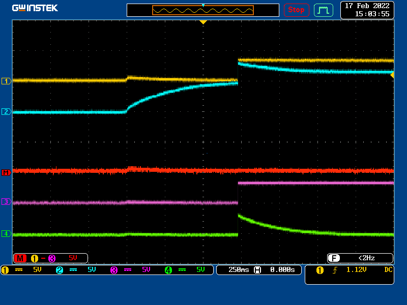
When we enable the amplifier, an audible click noise is perceived at the speaker (this also happens when both inputs are tied to GND).

What we want to know, is if there is a way to avoid the click noise during startup of the amplifier in this scenario?

I have attached the related schematics for your reference.

Thank you for your help!

  • Hi, 

    It doesn't appear like I am able to see the attached schematic. Can you try re attaching it?

    From your explanation is sounds like the pop noise may be coming from the rising edge of the Vbst voltage on the speaker. 

    if this is the case, then you may be able to alleviate some of the pop noise by increasing the 10kOhm resistor and the 2.2uF capacitor. this would increase the RC time constant and the rising edge seen by the speaker would be slower. this may make the noise less noticable.

    Arthur 

  • Hello Arthur,

    thanks for your hint! Something must have gone wrong in the upload.

    Find the schematic below:

    BR
    Michele

  • Hi Michele,

    thank you for re-attaching the schematic. 

    I think that all you can do in this case is slow the rising edge of the Vbst voltage.

    I would recommend increasing C402,C407, or R404

    Regards,

    Arthur

  • Hi Arthur,

    thanks for your hints, I was actually able to simulate that portion of the circuit and step through R404 between 10k and 100k.
    The results matched with what you had anticipated. However, increasing C402 and C407 had a much smaller impact compared to changing R404.
    Anyway, I also implemented the change in HW and the result looks (and sounds) good.

    You can see my scope recordings below.
    The first figure illustrates the measurement points.

    Here you can see the time behaviour of the signals (RED = MATH = CH1-CH3) before changing R404 to 100kOhm.

    This figure shows the curves after the change. (I swapped Channel 3 and 4 by accident).


    Out of curiosity; In the first scope shot you can see that Channel 3 (pink) shows a waveform that seems to resemble a discharge curve. I was wondering if this is a signal generated by the amplifier in consequence of the signal at it's OUT+ output?
    Basically the attempt of the amp to reduce the differential output signal because there is no difference at the inputs?

    Thank you very much for your help!
    Michele