


Part Number: PCM2707C
Other Parts Discussed in Thread: PCM2705C
Hello,
I would like to change the USB descriptor data with SPI.
What am i doing wrong here? 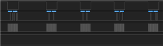
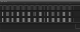
First line is CS, than the data and as a third the clock.
Both PSEL and host lines are high. D+ line is pulled low.
Thanks!
