Because of the Thanksgiving holiday in the U.S., TI E2E™ design support forum responses may be delayed from November 25 through December 2. Thank you for your patience.

This thread has been locked.

If you have a related question, please click the "Ask a related question" button in the top right corner. The newly created question will be automatically linked to this question.

LM4853: Adding 1k resistor between right output and ground (as in the datasheet) causes huge inrush current

Part Number: LM4853
Other Parts Discussed in Thread: TPS62056

I'm using an LM4853 in a portable device, powered from 4x AA batteries. This goes to a buck converter down to 3.3V, 800mA output (TPS62056), and then a boost converter to 5V, 1.5A output (MT3608). The LM4853 is powered by the 5V rail. The schematic I am following is from the LM4853 datasheet, with one difference - the headphone jack has a dedicated switch for headphone detect that doesn't interact with the left or right channels. Otherwise, I have everything connected exactly the same as below (the shutdown pin is permanently tied to GND, though, to allow activation at startup).
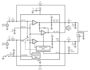
When I turn power on, with nearly depleted batteries and no headphones plugged in, the 3.3V/5V regulators struggle to come up. It appears to be too heavily loaded. If I disconnect the 1kΩ resistor on the right output, then everything acts normally - until I go to plug headphones in. There is a brief moment *before the headphone detection occurs* where the ring on the audio jack shorts the right output to GND. For some reason this heavily loads the regulators, and causes a brownout.

I've tried this with two separate LM4853 chips, one on a PCB and the other broken out onto a breadboard. Both do the same thing. The volume can be turned all the way off and it'll still occur. Is this a known issue with the amp?

  • Here's a scope capture of the issue in action when plugging in a headphone jack (or any audio jack) that causes the ring (right output) to be shorted to ground. Yellow is the left output, purple is the battery voltage, light blue is the right channel output, dark blue is the 3.3V supply. This was captured right after startup, so the bypass voltage has not charged up yet (hence why the right output channel hasn't reached V/2 or 2.5V yet). You can see where the light blue drops to zero is when the plug is inserted, and shorts the right output to GND. Note that this is measured *after* the electrolytic capacitor, directly on the headphone jack's right output.

    Also important to note - plugging in headphones doesn't cause any power issues. It can drive the headphones just fine. But shorting it, or even adding a constant 1k load to it, causes the power supply to really struggle.

    (I also think I had a case where plugging in headphones caused a huge dip on the power supply as well but it's not very repeatable)

  • Hi Nick,

    I'll take a look at all this description and provide some comments by tomorrow morning at the latest.

    Best regards,
    -Ivan Salazar
    Applications Engineer

  • Hey Ivan, were you able to check this out? Thanks.

  • Hi Nick,

    Any chance you can share more of your schematic? I'm specifically interested on the supply decoupling caps. Have you tried anything different on that part of the circuit?

    I'm curious about the DC bias on the output measurements, you say the scope is connected to the headphone jack, shouldn't the series capacitor block any DC coming from the amp?

    Best regards,
    -Ivan Salazar
    Applications Engineer

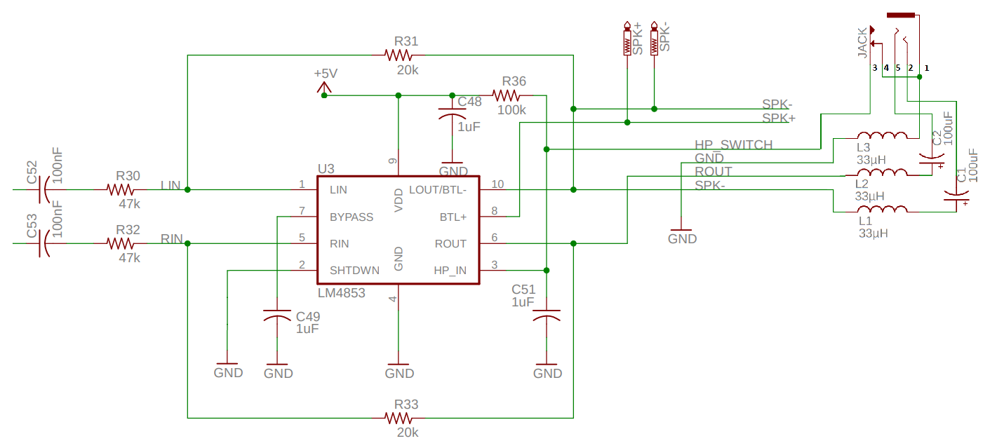
  • Sure thing. I should clarify, here is the "standard" schematic for my audio circuit:

    In the above scope trace, the 1k resistance RD1 was not included, it was captured on my "standard" schematic. I did not include it in the design because I'm not using the right channel for headphone detection; the jack I have has a separate switch for that (pins 3 and 4 on the headphone jack). But, when I encountered "Issue #1" - the power supply brownout after briefly shorting the right output to GND (which happens as one plugs headphones in) - I put RD1 back in so the output capacitor does not float (RD1 was a 1k resistor placed on the headphone jack right output, pin 5, to GND). I thought that perhaps shorting C2 above while plugging the headphones in caused some kind of inrush current into the DC blocking cap from the LM4853, and that adding a 1k to ground would remove that inrush.

    But, adding RD1 in caused "Issue #2" - the power supplies struggle to stabilize when turning the supply on. I would get constant brownouts for a few seconds, before finally entering a normal operating state. The 1k addition appeared to be loading down the supply. Which is odd, because plugging headphones in before turning it on does not cause this issue. It seems to me like ROUT does not like the 1k load in BTL mode, but in headphone mode it can handle the heavier load? That's the only thing I can conclude at the moment.


    Here is my power supply design. The PSU_EN is tied to VCC via a slide switch (debounced with an RC) to power up.


    VCC is typically around 4.8V to 5V; I'm using 4x series partially depleted NiMH batteries. What I see on the scope is the 3.3V supply being loaded down when the right output of the headphone jack connects to ground, or when it has the 1k load on it, and the output droops to 2V. Once it hits 2V, the MT3608 turns off, and the 5V rail fails. This removes the load from the system, and it tries again, resulting in a bootloop.

    Here are my attempts at fixing the issue:

    1) Increasing power supply capacitance on the 5V output (C4 in the power supply diagram). Increasing it to 100uF didn't help, doing larger values caused the supply to struggle to power on (even without RD1 included).

    2) Increased the LM4853 supply and bypass capacitance close to the chip (C48 and C49 in the audio schematic). Increasing both of these to 22uF did not make a difference.

    3) I added a 100 ohm resistor directly on the ROUT pin on the LM4853, before the node with the and the feedback resistor R33 and L3 inductor. Thought this would reduce any inrush current coming out of the pin that might be problematic. No effect.

    4) Tried a different LM4853 and performed tests on a breadboard instead of on my PCB. No change.

    5) Shorting the filters on the audio circuit (L1 - L3) didn't do anything. I thought maybe there was some chance that some complex impedance might be screwing something up or causing resonance - just an educated guess that was easy to test.

    My only other thought is that perhaps L1 or L2 on the power supplies are being saturated. I'm using Murata LQH3NPN100MMEL inductors, which have a max DC current rating of 1.12A and (if I'm reading the datasheet correctly) saturate at 810 mA. The rest of the loads on my design only appear to draw ~200mA from the supply, so I should have a decent amount of headroom. I could try designing new power supplies, but to me that sounds more like a band-aid rather than an actual solution to the issue, which seems to be something loading the supply down when ROUT is loaded on startup, or when ROUT DC blocking cap is shorted to ground.

  • Hi Nick,

    It may be useful to test the LM4853 portion only with an external bench supply, this way you can know from the supply itself how much current is being drawn by the device. You may try with the device in active and shutdown modes, with and without RD1 to better understand the behavior.

    Have you tried to remove C51? How did you decided to add this capacitor on HP_IN pin?

    Best regards,
    -Ivan Salazar
    Applications Engineer

  • I can use an external supply, but the one I have probably won't measure inrush or quick transients in current well. I think I'll have to add some sort of shunt to measure on a scope.

    C51 was added to essentially debounce the headphone/BTL transition. I don't know how important it is for actual operation. But I will note, HP-IN isn't changing states during this error, and it starts at GND through the headphone jack.

    Do you think adding external soft start on the shutdown pin could fix the issue? Do you see anything else troubling about the design?

  • Nick,

    Other than L1 to L3 and C51, the rest of the circuit looks close to the data sheet suggestion.

    Regarding shutdown pin, I just want to rule out some signals that are potentially related.
    Another thing to consider during debug would be output capacitors. Have you tried different material/type capacitors on C1/C2?
    Basic idea is to try to isolate the amplifier as best as possible, then start adding each of the additional parts of the circuit to identify if they contribute to the problematic behavior.

    Best regards,
    -Ivan Salazar
    Applications Engineer