This thread has been locked.

If you have a related question, please click the "Ask a related question" button in the top right corner. The newly created question will be automatically linked to this question.

DRV135: DRV135

Part Number: DRV135

Would connecting a lower load like 75 ohms to the two output pins of the driver (instead of 600 ohms) cause any damage to the driver or voltage signal?

I asked this question a couple months ago, but my DRV135 keeps getting damaged.  Attached is the circuit I'm using with 75 Ohms attached between DIFF_OUTPUT_HI_1 and DIFF_OUTPUT_LO_1 (not shown on image).  Is this the cause of damaging the audio drivers?
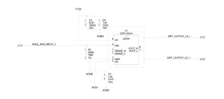
  • Hi Alexandra,

    The 75 Ohm connection alone should not damage the device.  Keep in mind that the device will go into current limit with a 75 Ohm load when the amplitude is too high, but this should not cause damage alone.

    I think there is something else causing a problem that is not captured on the schematic above.  Let me ask a few more questions:

    • How is the 75 Ohms connected?  Do you have cables running to it?  A fast transient on a long cable can cause a surge of current back into the device that could be destructive.
    • Is there only a 75 Ohm resistor connected between the differential output?  This must be connected to another downstream amplifier or input, correct?  Are they all powered with the same supply?
    • What are the signal amplitudes?  Is the voltage exceeding 3 Vpp?
    • What is the input source?
    • Is there an event that you can correlate to the failure, i.e. plugging in/out, powering up, etc?

    These answers will help us narrow down the root cause.

    Regards,
    Mike

    • How is the 75 Ohms connected?  Do you have cables running to it?  A fast transient on a long cable can cause a surge of current back into the device that could be destructive.
      • 75 Ohm load is connected via eight 600 Ohm resistors connected in parallel. There are cables connected, but they're only 3ft long.

    • Is there only a 75 Ohm resistor connected between the differential output?  This must be connected to another downstream amplifier or input, correct?  Are they all powered with the same supply?
      • The eight 600 Ohm resistors in parallel are connected to the differential output pair.  The Hi signal output is connected to DMM HI and LO signal is connected to DMM LO.  There is no receiving circuit/driver at the output end, they just go straight to the DMM.  Is a receiving circuit required?

    • What are the signal amplitudes?  Is the voltage exceeding 3 Vpp?
      • We're applying a 6Vpp Sine wave at 1kHz and a DC-Offset of 0V via a waveform generator.

    • What is the input source?
      • arbitrary waveform generator

    • Is there an event that you can correlate to the failure, i.e. plugging in/out, powering up, etc?
      • We haven't been able to find a specific even that correlates with the failure. We'll run it for a week or two multiple times and it'll work great. Then a couple weeks later the output signal starts degrading.
      • Seems like a good output differential signal will read about 2.1 Vrms and 0Vdc offset between HI and LO.  Then a few weeks later that "good" driver will start reading about 0.5-1.0 Vrms and 700mV Vdc offset. 

    Let me know your thoughts.

    Thanks,

    Alexandra

  • Hi Alexandra,

    OK, I think I understand now.  I supect that you are operating the device too close to current limit, and, as it heats up, the current limit will pull back to even lower values, then it will start to clip the amplitude, giving you lower RMS readings.  Then, the more it is clipped, potentially the hotter the device will get, causing current limit to roll back even further. 

    The device cannot drive 6 Vpp with a 75 ohm load; this would require 80 mApp of output drive, which is beyond the current at which the device goes into current limit.  If you try to drive it with 6 Vpp into 75 Ohms, it may be able to deliver the current at lower voltages, but will begin to clip at the peak voltages due to it going into current limit. Additionally, the current limit is strongly temperature dependent.  Going into current limit can actually cause a higher power dissipation, which will further heat the device up more.

    The chart below shows at what currents the output votage will start to collapse; as you can see, the current limit is around 85 mA for current sourcing, and 75 mA for current sinking.

    A few questions to test this theory; if you run the device at say, 1 Vpp, do the readings stay accurate and stable?  Can you look at a scope shot of the output to see if the signal is clipped?  Also, if you disconnect the load, and drive a much higher resistance (say, 1 kOhm), does the device work correctly, even if it did not seem to work correctly before?

    Regards,
    Mike

  • A few questions to test this theory; if you run the device at say, 1 Vpp, do the readings stay accurate and stable? 

    I ran the circuit at 1 Vpp with the 75 Ohm load still attached and read 0.41020 Vrms and 1.06 Dc-Offset.  I removed the load so it'd be open, and at 1 Vpp still read 0.4931 Vrms and 1.82 DC-Offset. Seems like the driver is still not accurate/stable at a lower stimulus. 

    Can you look at a scope shot of the output to see if the signal is clipped? 

    When i looked at the signal on the scope clipping was observed.

    Also, if you disconnect the load, and drive a much higher resistance (say, 1 kOhm), does the device work correctly, even if it did not seem to work correctly before?

    I disconnected the load and at 5 Vpp read 1.853 Vrms and 1.468 DC-Offset. 

    We have another circuit that uses the driver the same way, but with an open load between the output pins (no 75 Ohm load present).  The first couple of weeks we were measuring about 4.7 Vrms, but a couple weeks later the same degradation occurred in this circuit. Started measuring around 2 Vrms instead of the 4.7 Vrms like earlier.  Same input stimulus as the 75 Ohm load circuit. Any thoughts on this?

  • Alexandra,

    I simulated your circuit and I do not see an issue in simulation. Can you confirm that my schematic below matches your loading condition? Here is the simulation file:

    0552.DRV135.TSC

    This may not be creating the issue you are seeing however we recommend using DC blocking caps on the sense lines for applications driving long cables as shown below. 

    Can you provide us with oscilloscope shots that are DC coupled of both the input and the outputs?

    Best Regards,

    Chris Featherstone 

  • What is driving your DRV135's inputs?