This thread has been locked.

If you have a related question, please click the "Ask a related question" button in the top right corner. The newly created question will be automatically linked to this question.

LMV1015: Op-amp is attenuating signal instead of gaining - system seems powered properly

Part Number: LMV1015

Hello!

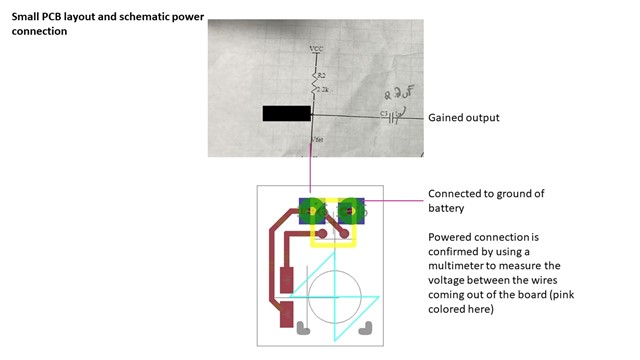
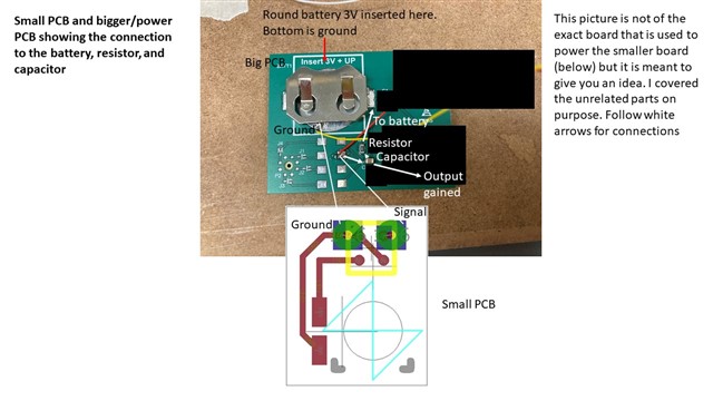
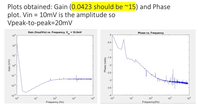
I need your help troubleshooting an op-amp (LMV1015-25) that should have a gain of about 16V/V but instead is attenuating my system. The op-amp is soldered on a small printed circuit board (PCB) and is powered through a bigger PCB (I will be including pictures below). In the small PCB I have two input pads (red) through which I can directly provide a voltage input signal (using probes). The output of the small PCB is obtained through the pads on the bottom layer (blue). The small PCB is powered as is instructed in the datasheet using a resistor, capacitor, and 3V battery. The resistor has a true value of 2.19kOhms and the capacitor a true value of 2.07uF. I have confirmed all connections using a multimeter and confirmed the small PCB is being provided power as well. Instead of a gain - my output through the op amp is actually attenuated (0.04 of the original input signal). The input signal (V peak-to-peak) is below the maximum (28mV) as instructed on the datasheet. Is there anything that I am missing that could be doing this? Thank you!

Datasheet: www.ti.com/.../lmv1015.pdf

  • Hi Panagiota,

    Since this device does not have too many pins or functions there are few things to consider. Are you using the same GND reference for both input and output? Perhaps the device is not getting properly powered up from VDD supply.

    Best regards,
    -Ivan Salazar
    Applications Engineer

  • The device is definitely powered - I used a multimeter to measure the power between the small wires that come out the small PCB (that are also used to extract the output from the device). I also know for sure that those wires make good connection between the small PCB and the big PCB (used the connectivity setting in the multimeter to check that). 

    As for the ground - I believe I am using the same one for the input and output signal (there is a ground input pad (red) that is connected to the ground output pad (blue) that is connected to one of the small wires that then is connected to the ground in the big PCB). Is there something more that I am missing here? 

    Thank you!

  • Panagiota,

    Is there any chance the IC was placed incorrectly, ie. rotated and input/output are swapped? Not sure if the signal would go through though..
    As mentioned, there should be not much that can be changed on a device like this. I'll try to check if there is any previous problem like this with a similar part. Have you tried different parts or all tests are on one unit only?

    Best regards,
    -Ivan Salazar
    Applications Engineer

  • Hi Ivan,

    I've tested 3 different devices all of which have a similar issue. I am currently not in my lab to continue testing - but I would think my next step is to try to test with a different power source (I am not sure how that would change much though). I was not the one who populated the devices on those PCBs but I would assume that I would not be getting an output if the device portals were flipped. Please let me know if you know anyone else who has had a similar issue with this or a similar device to this.

    Thank you.

    Best,

    Penny

  • Penny,

    Could you also try by removing the output capacitor? This should just affect the offset on the output signal, but want to check if this could be related somehow.
    I'll let you know if any findings about previous experience.

    Best regards,
    -Ivan Salazar
    Applications Engineer

  • Hi Ivan,

    Sorry for the delay in my response - I was out of town. I have a quick question: I see in the datasheet for the device that there is are Cin (input capacitance) and Zin (input impedance) values. Does that mean that I should have at least a 2pF capacitor across the input terminal (input-ground) of the op amp as I am supplying my input voltage of 10mV (20mV peak-to-peak)? As of now, I do not have anything connected at its input, I just have two probes that provide voltage directly to the terminals.

    Best,

    Penny

  • Hi Penny,

    That would not be a requirement for an input capacitor connected, to GND. although you may add a series AC coupling cap as general good practice to remove any DC from the source.

    Best regards,
    -Ivan Salazar
    Applications Engineer