This thread has been locked.

If you have a related question, please click the "Ask a related question" button in the top right corner. The newly created question will be automatically linked to this question.

ADC5140 random samples "sticking" to all 0 or all 1

Part Number: TLV320ADC5140
Other Parts Discussed in Thread: ADC5140EVM-PDK

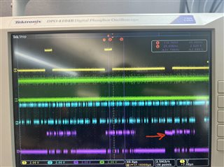
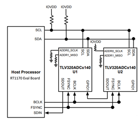
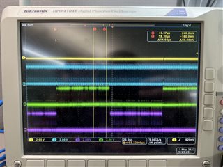
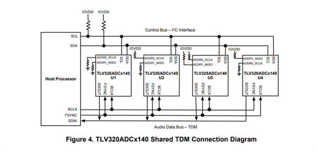
Hello!  I need some help on an issue where I have two ADC5140 ADCs configured in daisy chain mode (as per figure 9 in the app note : Multiple TLV320ADCx140 Devices With Shared TDM and I 2C Bus).  I am using TDM mode, 24 bits, 8 channels (4 from the first ADC, 4 from the second).  It is working for the most part, but randomly I am getting all 0's or all 1's from the first channel of the last ADC on the chain.  I have attached a scope shot that illustrates the issue.  My initialization code is as follows:

// Pull HW reset low, wait 10ms, then release

CLR_ADCMASTER_RESET;   
SysTick_Delay_ms(10);           
SET_ADCMASTER_RESET;
SysTick_Delay_ms(10);

//  ADC 1  /////////////////////////////////////////////////////////////////////////////////////////////////////////////////////////

LPI2C1_Write(I2C_ADDR_ADC1, ADCX140_PAGE_SELECT, 0x00); // Set page to zero
LPI2C1_Write(I2C_ADDR_ADC1, ADCX140_SLEEP_CFG, 0x81); // Wake up and enable AREG

SysTick_Delay_ms(10);

LPI2C1_Write(I2C_ADDR_ADC1, ADCX140_ASI_CFG0, 0x20);  // 24 bit words
LPI2C1_Write(I2C_ADDR_ADC1, ADCX140_ASI_CFG1, 0x00);
LPI2C1_Write(I2C_ADDR_ADC1, ADCX140_ASI_CH1, 0x00); // Mapped to default slots
LPI2C1_Write(I2C_ADDR_ADC1, ADCX140_ASI_CH2, 0x01); 
LPI2C1_Write(I2C_ADDR_ADC1, ADCX140_ASI_CH3, 0x02); 
LPI2C1_Write(I2C_ADDR_ADC1, ADCX140_ASI_CH4, 0x03); 
LPI2C1_Write(I2C_ADDR_ADC1, ADCX140_BIAS_CFG, 0x60); 
LPI2C1_Write(I2C_ADDR_ADC1, ADCX140_CH1_CFG0, 0x80); // Line input, differential, AC Coupled
LPI2C1_Write(I2C_ADDR_ADC1, ADCX140_CH2_CFG0, 0x80); // 
LPI2C1_Write(I2C_ADDR_ADC1, ADCX140_CH3_CFG0, 0x80); // 
LPI2C1_Write(I2C_ADDR_ADC1, ADCX140_CH4_CFG0, 0x80); // 
LPI2C1_Write(I2C_ADDR_ADC1, ADCX140_DSP_CFG0, 0x00); //

LPI2C1_Write(I2C_ADDR_ADC1, ADCX140_ASI_OUT_CH_EN, 0xf0); 
LPI2C1_Write(I2C_ADDR_ADC1, ADCX140_IN_CH_EN, 0xf0); 
LPI2C1_Write(I2C_ADDR_ADC1, ADCX140_PWR_CFG, 0x60); 

//  ADC 2  /////////////////////////////////////////////////////////////////////////////////////////////////////////////////////////

LPI2C1_Write(I2C_ADDR_ADC2, ADCX140_PAGE_SELECT, 0x00); // Set page to zero
LPI2C1_Write(I2C_ADDR_ADC2, ADCX140_SLEEP_CFG, 0x81); // Wake up and enable AREG

SysTick_Delay_ms(10);

LPI2C1_Write(I2C_ADDR_ADC2, ADCX140_ASI_CFG0, 0x20);
LPI2C1_Write(I2C_ADDR_ADC2, ADCX140_ASI_CFG1, 0x00); 
LPI2C1_Write(I2C_ADDR_ADC2, ADCX140_ASI_CFG2, 0x80); // Set up for Daisy Chain Mode
LPI2C1_Write(I2C_ADDR_ADC2, ADCX140_ASI_CH1, 0x00); //   Mapped to default slots
LPI2C1_Write(I2C_ADDR_ADC2, ADCX140_ASI_CH2, 0x01); //
LPI2C1_Write(I2C_ADDR_ADC2, ADCX140_ASI_CH3, 0x02); //
LPI2C1_Write(I2C_ADDR_ADC2, ADCX140_ASI_CH4, 0x03); //
LPI2C1_Write(I2C_ADDR_ADC2, ADCX140_GPIO_CFG0, 0xB0); // Make GPIO input for daisy chain
LPI2C1_Write(I2C_ADDR_ADC2, ADCX140_BIAS_CFG, 0x60); //
LPI2C1_Write(I2C_ADDR_ADC2, ADCX140_CH1_CFG0, 0x80); // Channel 1 configuration
LPI2C1_Write(I2C_ADDR_ADC2, ADCX140_CH2_CFG0, 0x80); // Channel 2 configuration
LPI2C1_Write(I2C_ADDR_ADC2, ADCX140_CH3_CFG0, 0x80); // Channel 3 configuration
LPI2C1_Write(I2C_ADDR_ADC2, ADCX140_CH4_CFG0, 0x80); // Channel 4 configuration
LPI2C1_Write(I2C_ADDR_ADC2, ADCX140_DSP_CFG0, 0x00);

LPI2C1_Write(I2C_ADDR_ADC2, ADCX140_ASI_OUT_CH_EN, 0xf0); 
LPI2C1_Write(I2C_ADDR_ADC2, ADCX140_IN_CH_EN, 0xf0); 
LPI2C1_Write(I2C_ADDR_ADC2, ADCX140_PWR_CFG, 0x60); 

Can anyone give me any hints on why I would be getting intermittent samples that are sticking to all 0's or 1's?  And only the first channel of the second ADC?

Thank you in advance everyone!

  • Quick update.  It seems as though the "error" is related to the input signals.  I am driving the inputs with two outputs of a function generator, offset by 180 degrees.  If the inputs are larger than about 20mVpp, then the issue arises.  However, I can see from the datasheet that the inputs (with AVDD =  IOVDD = 3.3V) can handle up to 2Vpp - so I am still confused.  Hopefully this helps!

  • Hi Bucky,

    Thanks for the extra info. Sanjay is the engineer who will look into this for you; you will hear from him soon.

    Thank you for your patience,

    Jeff

  • Can you please send me your schematic?

  • Hello Sanjay! 

    I don't have anything drawn up - but it is two of your ADC5140EVM-PDK boards (DC087 A) boards.  They are wired exactly as shown in figure 9 in the app note : Multiple TLV320ADCx140 Devices With Shared TDM and I2C Bus.  Although instead of 4 devices, there are only 2.

    The +inputs are all tied to a first channel of a function generator (1kHz, Phase = 0 degrees).  The -inputs are all tied to a second channel of a function generator (1kHz, Phase = 180 degrees).  The grounds of the generator are tied to the ground of the demo boards. The headers (J5 through J12) are removed such that the signals are AC coupled into the ADCs.  

    Thank you for your help.


  • For the second ADC can you try ASI_CHI for slot 4,5,6,7?

    LPI2C1_Write(I2C_ADDR_ADC2, ADCX140_ASI_CH1, 0x04); 
    LPI2C1_Write(I2C_ADDR_ADC2, ADCX140_ASI_CH2, 0x05); 
    LPI2C1_Write(I2C_ADDR_ADC2, ADCX140_ASI_CH3, 0x06); 
    LPI2C1_Write(I2C_ADDR_ADC2, ADCX140_ASI_CH4, 0x07); 

    Let me know if that helps

  • Hello Sanjay, thank you for the reply.  Here is what happens when I try your solution.

    Since the devices are daisy chained, moving the second ADC's data to slots 4 through 7 appears to remove it from the primary ADC's data stream (I assume its looking for the secondary ADC's data coming in on slots 0 through 3?)

    The app note (P14/P15) says "Note that channels of each device are mapped to slots 0-3", which is what led me to my original code.  

    Thank you again!

  • Best Regards

    Sanjay

  • Sorry about the Typo. Its a holiday today. I shall send a response to you tomorrow.

  • Still checking. Request time till tomorrow

  • Hi Bucky,

    Just checking if your issue is resolved now or if you are still waiting for an additional response? My interpretation of the original problem is that when neither ADC is transmitting on a slot, it will go hi-z and could float either high or low if there is nothing holding the bus.

    Brian

  • Hi Brian, 

    I actually got things working by making the first ADC run off of an external crystal and then daisy chaining it through the second ADC.  I haven't posted here because I still wanted to see what the solution to my original setup was - I was still waiting on Sanjay.

    The problem was that everything would work perfectly 95% of the time, but some random frames would have the first channel as what appears to be Hi-Z.  In the original scope shot you can see that the first two frames are fine, but then the third frame's first sample is wonky.

    Thanks!

  • Hi Bucky,

    I apologize for the delayed response. 

    Have you considered trying shared TDM? You have just 2 devices so the SDouts of the chips can be tied together without worrying about capacitive loading.

    In Daisy chaining where a loop through of the DATA happens and timing delays are a possibility. It might be a thought to try Shared TDM to see if you solve the issue