This thread has been locked.

If you have a related question, please click the "Ask a related question" button in the top right corner. The newly created question will be automatically linked to this question.

TPA3244: After measureing on outputs is nothing (AC or DC) on OUT pin, and on BST is about 12VDC. So if is possible to figure it out.

Part Number: TPA3244

Hi Team, 

I have some trouble with my TPA3244 amplifier. After cuple of days im trying to power up my layout board but when i meassure all supply power (PVDD 30V, VDD&GVDD 12V, Fault and clipOtw pin on 3,3v and reset on DVDD) and feed inputs with 1kHz 2,7Vpp signal from laboratory generator, on my output is not any signal. Amplifier is still consuming current about 0.06-0.07A an supply power is provided by laboratory source (for 30V) and tlm7805 (for 12V). After measureing on outputs is nothing (AC or DC) on OUT pin, and on BST is about 12VDC. So if is possible to figure it out.
Here is my scheme, im working on 2.1 output set (2xSE 1xBTL). So M1 is high and M2 on low.

Thanks.
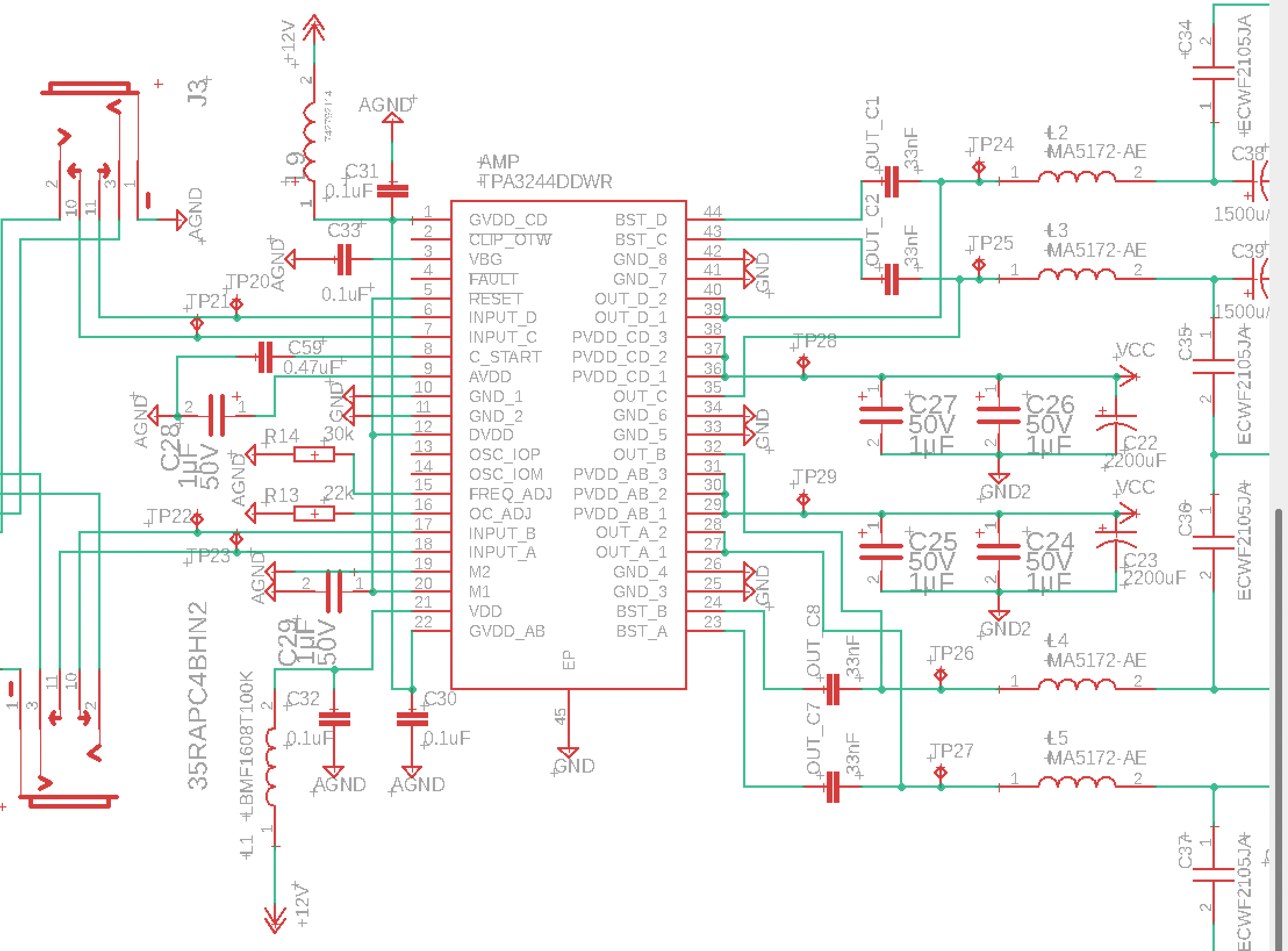
  • Here is my customer Email:xliska19@vutbr.cz

    He can't post

  • Hi Depeng

       Can you first check what is the state of FAULT and CLIP_OTW pin's state? Also, have you tried to use RESET pin to reset the device?

  • Hi 

    Thank you for your reply!, as i wrote, my clipOwt and fault pin is on high state (3,3V), and i also trying to reset device (which was working and when i set reset on low - avdd drop to low, and when i set reset back to high - avdd rise to approx. 7.8V), but on output is still no power, and i also try another input but same problem. My question is if is necessary to connect output load resistance of speaker to set amplifier to operate state. Because i was only measuring output of amplifier without load impedance, so maybe there is problem. 

    Thank you!
    I will try to change amplifier device, and try to make measurements on it.

    Best Regards

    James Man

  • Hi James

       I think the single ended side maybe causing the problem. Please remove the inductor L2 and L3 at the CD output side, and check if the problem can be solved. 

  • Hi Shadow,
    Thank you for your reply! As I followed typical application of TPA3244 of SE mode, are you sure to remove main inductor for PWM frequency filtering? I can try it, but no sure that's fix it. Thank you!
    Best Regards,
    James
  • Hi James

       I mean remove the inductor, so the SE side won't work. Only let the BTL side work and output power.

  • Hello and thank you for your advice,

    today i was trying to remove inductors on SE side of amplifier, but on BTL is still no output signal, so i think is something wrong with another part of my scheme. I was fed my input of BTL side with 1,2Vpp 100Hz signal from my generator, but on this signal was about 2mV of DC voltage, so maybe because of this DC part of signal amplifier wont be able to work. What do you think? Is there some reason why is my output still in HiZ state but fault, and owt_clip pins are on high normal state? and reset is working properly. on start amplifier consumes about 0,5A and after connect reset pin to high, it increase to 0,7A (still at 30V supply), but with no amplifying function.

    Thank you for yout advice, and have a great weekend as well!

  • Hi James.

    I think 2mVDC bias is not the reason of your problem. I have some questions need to confirm with you:

    1. I don't see the input decoupling capacitors in your schematic which is important to device startup, do you use the input decoupling capacitors?

    2. I notice that your Schematic has too much ground(AGND/GND/GND2), Are they the same terminal?

    Best Regards

    Wei Qiu.

  • Hi Wei, and thank you for your advice,

    (Mr. James Man was a mediator of communication on TI support, Thanks too.)

    input signal section is managed by PGA digital potentiometer, and before it is DC blocking 100pF cap parallel with 100ohm resistor and ferrite bead}showed on image). Maybe is necessary to add DC cap to output of PGA?

    But i was trying to fed input of amplifier with my laboratory generator at exact points on scheme named TP20, TP 21, 22, 23 which is connected directly to inputs of amp, but on output was nothing. So im very unhapy because im trying to solve my problem too long.

    And yes all GND is connected to one point where is connected together.

    Here is input section of amp:

    Thank you very much!!

    Bc. Matej Liska.

  • Hi Shadow,

    i removed these two inductors as you write above, but on BTL side isnt any signal at all.

    Maybe i can try remove inductors from BTL section too, and maybe it started work, but have you got another advice which i could try to solve my problem? 

    Thank you very much!

    Bc. Matej Liska.

  • Hi, Matej.

    The input decoupling capacitors are important to device startup, and the value we recommend is 10uF.

    can you add DC cap to the output of PGA and try again?

    Best regards.

    Wei Qiu.

  • Hi Wei.

    Today i add DC cap10uF to all input of amplifier, but nothing has changed. Amplifier still consume supply current about 0.06A and when i fed inputs with normal 1kHz sine signal from my laboratory generator on output is nothing. (CLIP, OWT and FAULT pin still on high normal state) so there must be something wrong in other part of scheme.

    Is there some information why can be all outputs still in HiZ state?

    Thank you.

  • Hi, Matej.

    Can you observe the RESET, INPUTA, INPUTB, OUTA(OUTB) waveform at  the same time, and post the waveform for us to have a further analyze?

    Best regards.

    Wei Qiu.