This thread has been locked.

If you have a related question, please click the "Ask a related question" button in the top right corner. The newly created question will be automatically linked to this question.

TAS5828M: Hybrid Feedback PWM not working as described

Part Number: TAS5828M
Other Parts Discussed in Thread: LM3478

Hello,

I am configuring the TAS5828M and I'm having difficulty getting the hybrid feedback PWM mode configured correctly. I have set up the configuration in PPC3 for PBTL (Base/Pro 1.0 48K) mode. I have enabled the Hybrid Pro block and set it for a voltage min of 5.5V and max of 20V with 384kHz PWM and implemented the circuit described in the tool in my custom hardware.  I have also enabled the PVDD/AGL/OTFB block and set GPIO1 as Class H in the advanced SRT window.

I see that the GPIO1 pin is providing a PWM signal and it is able to have an impact on the supply voltage through the filter and feedback network connections, but the signal does not switch at 384 kHz and does not reach the max or min voltages under any conditions. 

Does the Base/Pro 1.0/48K mode support Hybrid PWM feedback? Have I misconfigured a register perhaps? Could it be that the issues I am experiencing are due to the (I think) preproduction version of this device? The amplifiers on my board say PTAS5828M on the top. 

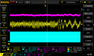
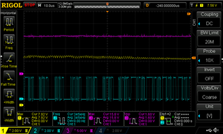
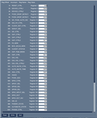
I have included an excerpt of my schematic showing the amplifier and boost designs, as well as the PPC3 file I have configured, screenshots from a python tool showing the TAS5828M registers while playing music, and a series of scope traces.

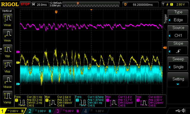
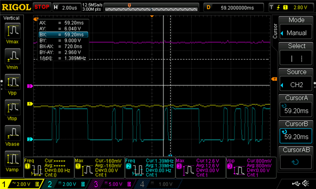
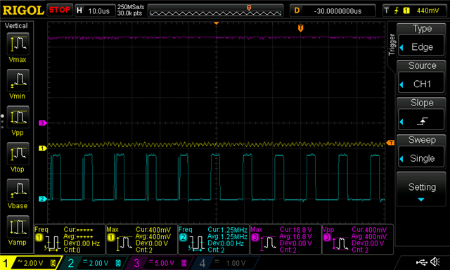
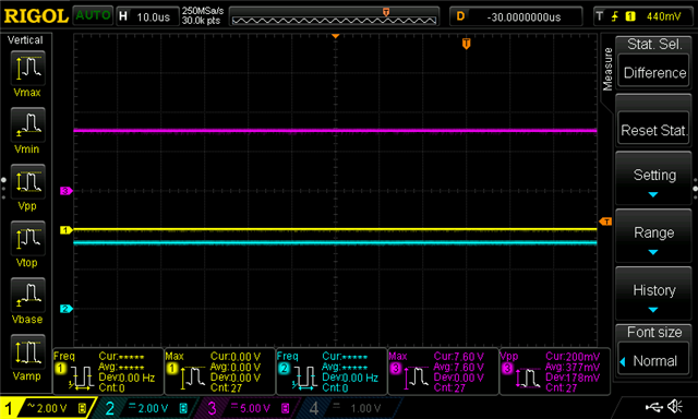
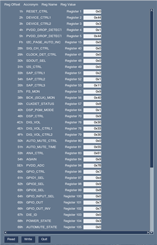
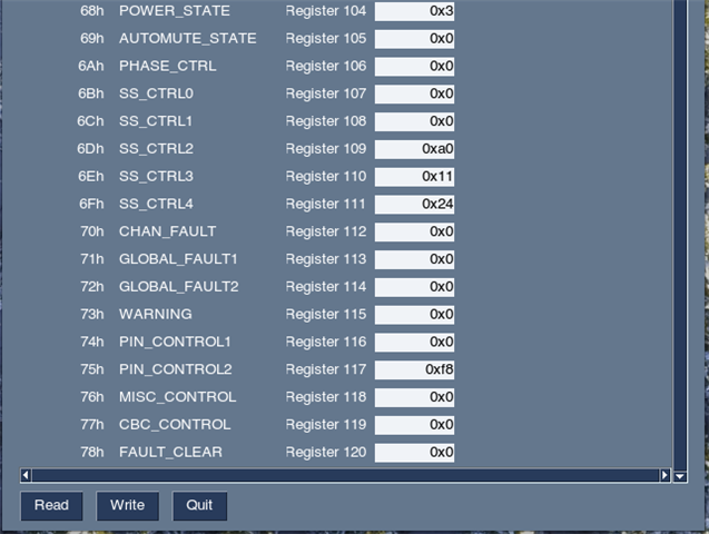
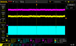
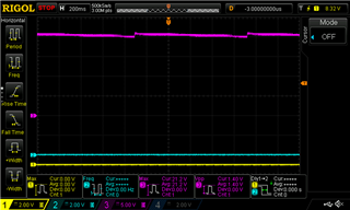
Image_1 shows the SPK_L+ signal (AC coupled) in yellow, the Hybrid Feedback PWM pin (GPIO1) in blue, and PVDD in purple under the conditions of playing music ad med-high volume. Image_2 shows the same trace zoomed in to see the PWM frequency. Image_3 shows the same traces playing music with 0 volume, and Image_4 shows the same traces with music paused.

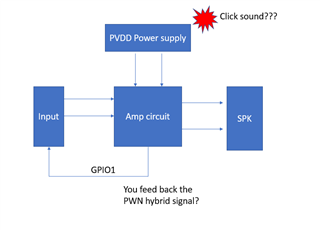
The audio from the amplifier sounds great, my only problem/symptom is that the hybrid PWM signal induces a clicking in the power supply that is especially apparent while playing at low volumes (but goes away when music is paused).

Any ideas what is going wrong for my application? Your assistance is greatly appreciated.

Best regards,

Craig Verrill

    TAS5828M.pdf

  • Hi Verrill

    You want to use Base/Pro 1.0/48K mode with Hybrid PWM feedback?

    I am afraid that only Base/Pro 1.0/96K hybrid mode support the Hybrid PWM feedback.

    Jesse

  • Hi Jesse,

    I have reconfigured the PPC3 file for  Base/Pro Hybrid 1.0 96k and enabled the Hybrid-Pro feature and set it to GPIO1 using the SRT portion of the tool. I still hear clicking from my boost power stage which can only be eliminated if the connection between the TAS5828M's GPIO1 and the boost feedback terminal is broken,

    Do you know what I am doing wrong here or what is mis-configured? It does look like the PVDD rail is influenced by the hybrid feedback pin and goes in the appropriate direction, but I am not able to eliminate the buzzing sound produced by the boost converter when hybrid-pwm is enabled.

    The first scope trace shows the SPK_L signal in yellow, the hybrid PWM pin in blue and PVDD in purple while music is playing loudly. The second trace shows the same thing zoomed in. The third trace shows the same signals while music plays at 0 volume and the final trace is after the music has been paused. I have also included a display of the device registers while playing and my full PPC3 output file (was not able to upload the original .PPC3 file but can send via email if necessary).

    Thanks and regards,

    Craig

    Loud Music

    Loud Music zoomed-inhybrid_pwm_pbtl_full.h

    Quiet Music

    Paused Music

    Registers 1

    Registers 2

  • Hi Verrill

    let me clear some thing for better understanding.

    you mean the click sound comes from the power supply, not the connected speaker?

    I draw a simple block diagram about your system, am i understanding right?

    if you reduce the output power level, does the click sound become smaller or disappear?

    if my understanding is not right, can you draw me a simple block of your system.

    you can send me the ppc3 file by email. if you cannot solve the problem, i can use your configure with our EVM board to confirm the issue.

    thanks.

    Jesse

  • Hi Jesse, 

    Your block diagram shows the connections between the input, amplifier and speaker as I have them, but the GPIO1 pin instead goes to the PVDD power supply feedback network. The clicking sound does come from the boost converter that powers PVDD, and it occurs even if no speaker is connected to the system and even if no Bluetooth audio source is connected to the Bluetooth audio sink (input block on the diagram).

    Best regards,

    Craig 

  • HI Craig

    I am not sure what kind of PVDD power supply device you use.

    Is there any instruction of power supply device, does it give any hint about what kind of situation will generate the click? current is too large or the load is too small?

    thanks.

    Jesse

  • Hi Jesse,

    We are using the LM3478 with 7.2V battery as its input to drive the PVDD power supply. There is a PDF schematic attached to the initial question showing our schematics for the audio and power stages. 

    I separated the audio amplifier hybrid PWM signal from the boost feedback and checked the boost and audio stages independently. I saw that the hybrid PWM signal looked as described and the boost converter was generally quiet but occasionally made an audible click sound. Next I looked at the compensation network on the boost stage and saw that it was generally steady and regulated (with hybrid PWM disconnected from FB still)  at 0.828V but would occasionally spike up to 1.4V and that coincided with the timing of the clicks I hear.

    Based on that observation, I'm pretty sure the issue is in my boost compensation network on the LM3478. After reconnecting the hybrid PWM signal to the FB network, I looked at the compensation network voltage again and saw that it was all over the place, switching rapidly between around 0.8V and 1.4V.

    Is there any special guidance on choosing the compensation components once the Hybrid PWM feature comes into play? Can you double-check the compensation with me and help determine if it should work or if its way off?

    Thanks and regards,

    Craig

  • Hi Craig

    Can you provide me the circuit schematic by e-mail?

    My e-mail is jesse-ji@ti.com.

    myside is mainly focus on the amplifier related issue, if the problem is related to how to use LM3478, I am not sure whether need to transfer to other department to support you.

    if possible, please let me confirm the circuit schematic including the power supply and audio amplifier part.

    By the way, just for confirm, when the click happened, does the audio amplifier work normal or not?

    is there any error been triggered?

    thanks.

    Jesse.

  • Hi Jesse,

    In this situation, the audio amplifier portion of the circuit does work normally. Stand by and I'll email you the schematic.

    Thanks and regards,

    Craig