This thread has been locked.

If you have a related question, please click the "Ask a related question" button in the top right corner. The newly created question will be automatically linked to this question.

TLV320AIC3106: LCDKOMAPL138 - AIC3106 CODEC

Part Number: TLV320AIC3106

Hello,

I have been trying the increase the level of my signal that coming out of LINEOUT of the AIC3106 codec via implementing various configurations of AGC. At present with following register settings (Register :

Codec_RSET( LEFT_AGC_A, 0 ); // AGC off

Codec_RSET( RIGHT_AGC_A, 0 ); // AGC off 

Codec_RSET( LEFT_AGC_B, 0x00 ); // AGC max gain=0

Codec_RSET( RIGHT_AGC_B, 0x00 ); // AGC max gain=0

Codec_RSET(LEFT_AGC_C, 0x00);   // Hysteresis disabled, noise/silence disabled and AGC clip stepping disabled
Codec_RSET(RIGHT_AGC_C, 0x00);

Codec_RSET(LEFT_AGC_Gain, 0x00);   // 0dB gain
Codec_RSET(RIGHT_AGC_Gain, 0x00);  // 0dB gain

Codec_RSET(LEFT_AGC_Noise_Gate_Debounce, 0x00);   // Noise detection debounce control  = 0msec, Signal detection debounce control = 0msec

Codec_RSET(RIGHT_AGC_Noise_Gate_Debounce, 0x00);

with these configuration, my signal's amplitude comes out to be 121mV. I am trying to increase it to 600mV. But even if I change the above configurations to, 

Codec_RSET( LEFT_AGC_A, 0x80 ); //  AGC enable, AGC target level = -5.5dB, AGC attack time = 8msec, AGC decay time = 100msec

Codec_RSET( RIGHT_AGC_A, 0x80); //  AGC enable, AGC target level = -5.5dB, AGC attack time = 8msec, AGC decay time = 100msec

Codec_RSET( LEFT_AGC_B, 0xFE); // AGC max gain=59.5dB

Codec_RSET( RIGHT_AGC_B, 0xFE ); // AGC max gain=59.5dB

Codec_RSET(LEFT_AGC_C, 0x7F);   // Hysteresis = 2dB, Noise Threshold Control = -90dB, AGC clip stepping control = enabled
Codec_RSET(RIGHT_AGC_C, 0x7F);

Codec_RSET(LEFT_AGC_Gain, 0x77);   // 59.5dB gain 
Codec_RSET(RIGHT_AGC_Gain, 0x77);  // 59.5dB gain

Codec_RSET(LEFT_AGC_Noise_Gate_Debounce, 0x00);   // Noise detection debounce control  = 0msec, Signal detection debounce control = 0msec

Codec_RSET(RIGHT_AGC_Noise_Gate_Debounce, 0x00);

My signal level isn't increasing from 121mV. I have trouble understanding why? Kindly, help me understand how can I observe AGC in the codec and why despite changing the configuration, the AGC isn't increasing the level. Thank you.

  • Waseem,

    Can you check the ADC Flag Register (Register 36) to see if the gain is being applied by the AGC? Make sure you aren't writing over LEFT/RIGHT_AGC_Gain. That's a monitor of the gain being applied. Where are you measuring the 121Vrms from?

    Best regards,
    Jeff

  • Hello,

    I apologize that it took long for the response. I am measuring the 121Vrms from Left Line Output (Left LOP/M) as you can see in the figure. 

    After adjusting the registers 85 and 86, with 85 being the  DAC_R1 to LEFT_LOP/M Volume Control Register routed to LEFT_LOP/M with 0dB analog gain applied. And 86 register adjusting the Left LO output level from 0 to 9dB. From this, I have managed to adjust the Left Line output level and measured that via the Left Line Output port as shown in the figure above on the oscilloscope. My lowest level is 234mV and the highest level (9dB) is 647mV. 

    On the ADC side, I am measuring the affect of AGC from the DOUT pin which is pin 41 of the codec as shown in the figure, 

    But, my concern is that I am having trouble understanding the affect of AGC. What ratio does it change when I change the register values? What register should I change for observing its affect? AGC registers are from 26 to 36. You mentioned that I should check register 36, how should I check its affect from DOUT pin? 

    Also, if I want to decrease my voltage level at the ADC side, which registers should I use? So that I prevent saturation of my signal. 

    Another concern regarding this codec is that what maximum voltage can it take at the ADC side. I have been facing the issue that when the kit (LCDKOMAPL138) is properly grounded then the codec doesn't get damaged. When it isn't, the ADC gets damaged and I have to change the IC for that. How should I prevent that from happening since in some cases my signal gets saturated or there is no signal when I ground the kit properly. 

    Regards,

    Waseem

  • Hi Waseem,

    The AGC will dynamically adjust the PGA gain to maintain a certain target output level. The register values control parameters such as attack and decay time, noise gate, etc. The effect of the AGC is hard to observe on the pin itself. It's best seen in the analog time domain.

    To prevent clipping you'll want to adjust the PGA gain, but keep in mind that the AGC will take control of this when active.

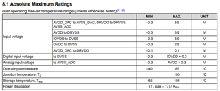
    Table 8.1 lists the maximum ratings with respect to grounds.

    Best regards,

    Jeff

  • Hello Jeff,

    Regarding the maximum ratings, the LINEIN port input voltage level mustn't exceed 707mV (0.707 Vrms) right? Even if the LINEIN port's voltage isn't receiving this level and only receiving about 240mV Vrms, the LINEIN port gets damaged particularly the ADC pin and the C172 capacitor that is in the path of the Left Line IN gets damaged. I have trouble understanding the issue. 

    Regards,

    Waseem

  • Hi Waseem,

    You are correct the full scale voltage is 707mV. This is the limit before clipping. The limit before damage occurs is AVDD+0.3 V. Be aware that these ratings are with respect to certain grounds (They are in the table above). So as you mentioned the device does need to be grounded properly to avoid damage.

    Best regards,

    Jeff

  • Hello Jeff,

    Thank you for your response. I have another query. If at the ADC side, I receive a signal of 37mV and I want to increase the signal level at the ADC side, what codec registers should I use to increase that level? 

    Regards,

    Waseem

  • Hi Waseem,

    You should adjust registers 15 and 16. These control the PGA gain on the left and right channels before the ADC.

    Best regards,

    Jeff

  • Hello Jeff,

    For the PGA gain, you mentioned the AGC would take control to maintain certain target level and that it's better to observe it's affect in the analog domain. By that do you mean observe it's affect before ADC? The PGA is preceded by the ADC. So that means that if I follow through, I can observe its affect on LEFT_LOP without adjusting Register 86 as shown in the figure? 

    Regards,

    Waseem

  • Hi Waseem,

    Yes the bypass line can work for that. However you shouldn't have to precede the ADC as long as the DAC is also in the path. I simply mean measuring the signal in the digital domain without a digital to analog analyzer isn't a good way to measure the AGC.

    Best regards,

    Jeff

  • Hello Jeff,

    Thank you for your response. I will check this. Thank you.

    Regards,

    Waseem

  • Hi Waseem,

    For record keeping purposes, please wait to reply until you have an update. This thread will stay open while we wait on your end.

    Thank you,

    Jeff