This thread has been locked.

If you have a related question, please click the "Ask a related question" button in the top right corner. The newly created question will be automatically linked to this question.

How do we configure the PCM mode of the TLV320AIC3106?

Other Parts Discussed in Thread: TLV320AIC3106

Hi, TI expert

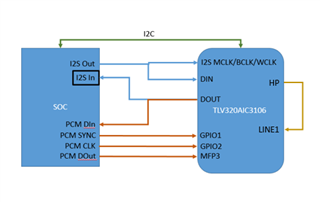
I am planing to use the TLV320AIC3106 to test I2S Out/In and PCM Out/In interfaces of the SOC with a loopback mode. The testing concept is below. 

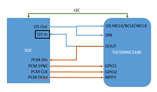
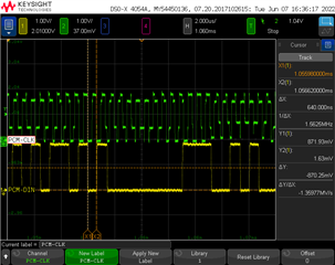
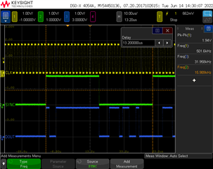
Now we are focusing on the PCM Out/In interface (I2S interface is ignored). My problem is the we can see the signal waveform at PCM SYNC, PCM CLK, and PCM DOut with a scope, but we do not see the signal waveform at PCM DIn. My initial code is below. I believe the initial code should have some problems. May I have your review and comments? Thank you!

function codec()
{
if [ ! -d /sys/class/gpio/gpio${codec_rst_pin} ] ; then
echo ${codec_rst_pin} > /sys/class/gpio/export
fi
echo out > /sys/class/gpio/gpio${codec_rst_pin}/direction
echo 1 > /sys/class/gpio/gpio${codec_rst_pin}/value
sleep 1
echo "PCM Test Mode"
i2cset -f -y $codec_i2c_bus $codec_addr 0x01 0x80 b
i2cset -f -y $codec_i2c_bus $codec_addr 0x07 0x8A b
# GPIO1 = word clock for audio serial data bus (programmable as input or output)
i2cset -f -y $codec_i2c_bus $codec_addr 0x62 0xB0 b
# GPIO2 = bit clock for audio serial data bus (programmable as input or output)
i2cset -f -y $codec_i2c_bus $codec_addr 0x63 0x80 b
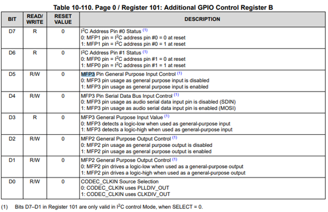
# MFP3 pin usage as audio serial data input pin is enabled (MOSI)
i2cset -f -y $codec_i2c_bus $codec_addr 0x65 0x10 b
i2cset -f -y $codec_i2c_bus $codec_addr 0x08 0xC0 b
i2cset -f -y $codec_i2c_bus $codec_addr 0x29 0x02 b
i2cset -f -y $codec_i2c_bus $codec_addr 0x2B 0x00 b
i2cset -f -y $codec_i2c_bus $codec_addr 0x25 0xD0 b
i2cset -f -y $codec_i2c_bus $codec_addr 0x40 0x80 b
i2cset -f -y $codec_i2c_bus $codec_addr 0x2F 0x80 b
i2cset -f -y $codec_i2c_bus $codec_addr 0x33 0x0D b
i2cset -f -y $codec_i2c_bus $codec_addr 0x41 0x0D b
}

BR

Kevin


  • Hi Kevin,

    It seems you are writing 0x10 to Register 101 (0x65) which is making the MFP3 Pin act as the SPI MOSI function, not the SDIN function. Try 0x00.


    Best regards,

    Jeff

  • Hi Jeff,

    Thanks for your response. After trying 0x00, the result is the same as before. I do not see the waveform at DOUT pin (DOUT --> PCM DIN). Is it possible the I2S function still works becaue I do not configure it (all setting for I2S is default in codec).

  • Hi Kevin,

    Looking back through your code again, you have BCLK and WCLK set as outputs/master mode, which contradicts your diagram. I assume you mean for the SOC to be the master? Can you also share a scope capture of the clocks and where you are measuring them?

    Thank you,

    Jeff

  • Hi Jeff,

    Thank you! I will provide the scope capture. Before that, please allow me have more description for the block diagram in detail. We need to verify the I2S IN and OUT interface and the PCM IN and OUT of the SOC with the codec. We use the aplay command to play a 1KHz tone WAV at I2S OUT and use the arecord command to record the WAV at I2S IN interface. Actually, we do not configure the I2S OUT as the master mode and the I2S IN as the slave mode. We are focusing on the PCM function. So we can ignore the I2S part from the diagram. I will provide the scope capture of the PCM. Thank you!

    BR

    Kevin

  • Hi, Jeff

    Should I configure the Register 9? If yes, I do not see the suitable item for the PCM mode.

    BR

    Kevin

  • Hi, Jeff

    Have you any good news? 

    BR

    Kevin

  • Hi, Jeff

    Have you any good news? 

    BR

    Kevin

  • Hi Kevin,

    Jeff has been out of office the past week. Sorry for the delay. He will be back tomorrow and can respond at that time.

    Brian

  • Yes, no problem. 

    I measured the clk at the "GPIO2" pin and the data at the "MFP3" pin.

  • Hi Kevin, thank you for your patience,

    Yes Register 9 needs to be configured. Even though there are different pins for the I2S and PCM data buses, they are muxed into the same audio interface, so the configuration needs to be done.

    Thank you for sharing the plot. The clock has some odd distortions in it that may be affecting the performance. You can see the high and low levels are changing, and there are spikes on the edges that last for some time. I would try to clean that signal.

    However I still want to clarify the software. What I was asking about master slave mode was in Register 8. It refers to both WCLK/GPIO1 and BLCK/GPIO2 based on which bus is intended to be used. The configuration is shared by both buses and needs to be correct. If you intend for the AIC3106 to be the master that should be fine, as long as the SOC is set up for it. I wanted to clarify that because it appears like you want the AIC3106 to be the slave according to the diagram.

    Best regards,

    Jeff

  • Hi, Jeff

    Welcome back! Slight smile 

    Regarding the master/slave mode setting, my assumption is the CPU is the master. If my assumption will have impact for the codec, we can configure the codec as the master mode.  We would like to have full register setting based on this mode change. Please have your full support for this issue because of my schedule concern. Thank you!

    BR

    Kevin

  • Hi, Jeff

    My mode setting is the codec is the master mode. I will try the slave mode. My assumption is the different mode between the slave and master is who to generate the BCLK and WCLK. If I am wrong, please let me know. Thank you!

    BR

    Kevin

  • Hi, Jeff

    I have configured the codec to be slave mode by modifying the Register 8 (its value is 0x00), but the scope does not detatc the signal at the DOUT pin. Have you any ideas? Thank you!

    BR

    Kevin

  • Hi Kevin,

    You are correct that the master slave distinction is who is generating the clocks. If something other than the codec is generating the clocks it needs to be in slave mode.

    The clock distortions still concern me. I know we are ignoring the i2s port for now, but has it worked with this setup? It would help to isolate between a hardware or software issue.

    Best regards,

    Jeff

  • Hi, Jeff

    How does the codec decide or identify the audio signal form I2S or PCM? The following is my setting sequence to combine the PCM and I2S, and connects the HP (ROUT, LOUT) to the LINE1 (RP, LP) to do external loopback. Please help take a look it. Thank you!

    i2cset -f -y $codec_i2c_bus $codec_addr 0x09 0x30 b

    i2cset -f -y $codec_i2c_bus $codec_addr 0x0A 0x00 b

    i2cset -f -y $codec_i2c_bus $codec_addr 0x07 0x8A b
    i2cset -f -y $codec_i2c_bus $codec_addr 0x62 0xB0 b
    i2cset -f -y $codec_i2c_bus $codec_addr 0x63 0x80 b
    i2cset -f -y $codec_i2c_bus $codec_addr 0x65 0x00 b
    i2cset -f -y $codec_i2c_bus $codec_addr 0x29 0x02 b
    i2cset -f -y $codec_i2c_bus $codec_addr 0x2B 0x00 b
    i2cset -f -y $codec_i2c_bus $codec_addr 0x0E 0xC0 b
    i2cset -f -y $codec_i2c_bus $codec_addr 0x25 0xE0 b
    i2cset -f -y $codec_i2c_bus $codec_addr 0x26 0x10 b
    i2cset -f -y $codec_i2c_bus $codec_addr 0x2F 0x80 b
    i2cset -f -y $codec_i2c_bus $codec_addr 0x40 0x80 b
    i2cset -f -y $codec_i2c_bus $codec_addr 0x41 0x0D b
    i2cset -f -y $codec_i2c_bus $codec_addr 0x33 0x0D b
    # Line-IN setting
    i2cset -f -y $codec_i2c_bus $codec_addr 0x1F 0xF8 b
    i2cset -f -y $codec_i2c_bus $codec_addr 0x15 0xF8 b
    i2cset -f -y $codec_i2c_bus $codec_addr 0x16 0x84 b
    i2cset -f -y $codec_i2c_bus $codec_addr 0x13 0x84 b
    i2cset -f -y $codec_i2c_bus $codec_addr 0x0F 0x00 b
    i2cset -f -y $codec_i2c_bus $codec_addr 0x10 0x00 b

    i2cset -f -y $codec_i2c_bus $codec_addr 0x66 0xA0 b

    BR

    Kevin

  • Updated the block diagram.

  • BTW, may I connect the PCM of the SOC to the I2S of the codec?

    BR

    Kevin 

  • Hi Kevin,

    You should be able to connect the PCM of the SOC to the I2S. The codec decides which to listen to (PCM or I2S ports) via Register 98, 99, and 101 (GPIOX and MFP3 controls). Registers 8 and 9 control the Audio Interface, whose inputs are muxed between PCM and I2S.

    Best regards,

    Jeff

  • One more questions, please.

    1) How does the codec handle the resolution from I2S or PCM? In my system, the resolution of I2S is the 32-bit and the PCM is the 16-bit resolution.

    2) May I have your comment for my full register setting I post on June 9.

    Thank you!

    Kevin

  • Hi Kevin,

    I didn't see any issues with the code.

    The resolution change is done by configuring the audio interface. Keep in mind that the codec does not handle both buses simultaneously. It choses one according to the register settings. This handoff should be accompanied by an audio interface reconfiguration to match.

    Our codec expert should be returning Monday, and he may see something that I don't.

    Best regards,

    Jeff

  • Hi, Jeff

    I have connected the PCM_CLK pin to the BCLK pin, the PCM_SYNC pin to the WCLK pin, and the PCM_DOUT to the DIN pin. The scope result is I measured at the BCLK, WCLK, and DIN pins, but I do not detect the waveform at the DOUT pin. The WAV source file is 16K with PCM-16bit format. 

    Based on the using the 16K WAV file in stead of the 44.1K WAV file, I also modify the codec initial code as below, Please have your comment. Thank you!

    i2cset -f -y $codec_i2c_bus $codec_addr 0x08 0x00 b
    i2cset -f -y $codec_i2c_bus $codec_addr 0x09 0x00 b

    i2cset -f -y $codec_i2c_bus $codec_addr 0x0A 0x00 b

    i2cset -f -y $codec_i2c_bus $codec_addr 0x07 0x8A b
    i2cset -f -y $codec_i2c_bus $codec_addr 0x29 0x02 b
    i2cset -f -y $codec_i2c_bus $codec_addr 0x2B 0x00 b
    i2cset -f -y $codec_i2c_bus $codec_addr 0x0E 0xC0 b
    i2cset -f -y $codec_i2c_bus $codec_addr 0x25 0xE0 b
    2cset -f -y $codec_i2c_bus $codec_addr 0x26 0x10 b
    i2cset -f -y $codec_i2c_bus $codec_addr 0x2F 0x80 b
    i2cset -f -y $codec_i2c_bus $codec_addr 0x40 0x80 b
    i2cset -f -y $codec_i2c_bus $codec_addr 0x41 0x0D b
    i2cset -f -y $codec_i2c_bus $codec_addr 0x33 0x0D b
    i2cset -f -y $codec_i2c_bus $codec_addr 0x1F 0xF8 b
    i2cset -f -y $codec_i2c_bus $codec_addr 0x15 0xF8 b
    i2cset -f -y $codec_i2c_bus $codec_addr 0x16 0x84 b
    i2cset -f -y $codec_i2c_bus $codec_addr 0x13 0x84 b
    i2cset -f -y $codec_i2c_bus $codec_addr 0x0F 0x00 b
    i2cset -f -y $codec_i2c_bus $codec_addr 0x10 0x00 b

    i2cset -f -y $codec_i2c_bus $codec_addr 0x66 0xA0 b

    BR

    Kevin

  • Hi Kevin,

    So what you are trying to do is to send signal say from I2S to HP and route it back through LINE1 and capture with PCM as one of the test case - correct?

    Let's break it down for clarity and you can combine once it's verified.

    1) I2S Out from SoC to codec with HP AC-coupled output settings:

    w 30 07 8A (fs=44.1KHz)
    w 30 08 00 (codec in slave mode)
    w 30 09 00 (i2s mode with 16 data length)
    w 30 29 02 (L1 and R1 DAC path)
    w 30 2B 00 (0dB LDAC)
    w 30 2C 00 (0dB RDAC)
    w 30 0E C0 (ac-coupled driver and differential)
    w 30 25 E0 (power up LDAC/RDAC and HPLCOM as independent output)
    w 30 26 10 (HPRCOM as independent output)
    w 30 2F 80 (DAC L1 to HPLOUT with 0dB)
    w 30 40 80 (DAC R1 to HPROUT with 0dB)
    w 30 41 0D (HPROUT power up with 0dB)
    w 30 33 0D (HPLOUT power up with 0dB)

    Please verify your SoC WCLK and BCLK per the above settings and check HP output.

    2) LINE1 input to PCM interface output settings:

    w 30 08 00 (codec in slave mode)
    w 30 09 40 (DSP mode with 16 data length)
    w 30 62 B0 (GPIO1 as PCM WCLK)
    w 30 63 80 (GPIO2 as PCM BCLK)
    w 30 65 21 (MFP3 is enabled as audio input)
    w 30 15 F8 (set LINE1R differential)
    w 30 16 84 (set LINE1R 0dB and power up Right ADC)
    w 30 13 84 (Power up Left ADC and set LINE1L differential to left ADC 0dB)
    w 30 0F 00 (Left ADC 0dB)
    w 30 10 00 (Right ADC 0dB)

    Please verify your SoC PCMCLK and PCMSYNC per the above setting.

    Regards.

  • Hi, Pdjuandi,

    I have tested the loopback function with your command. The testing result is perfect. The audio codec can translate the PCM OUT to PCM IN. Thank you so much!!

    BR

    Kevin

  • You are welcome.

  • You are welcome.