Hello!
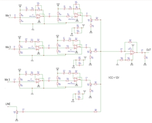
I am making a portable speaker system. Powered by 12V battery.
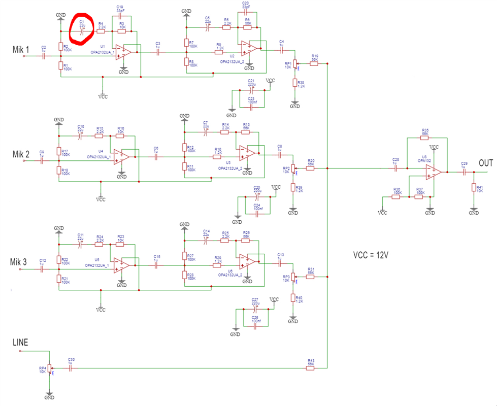
Can you please tell me if capacitors C19 and C20 are required?
Perhaps there are more tips for this scheme? Does this design contain errors and inaccuracies?
 Thank you!
This thread has been locked.
If you have a related question, please click the "Ask a related question" button in the top right corner. The newly created question will be automatically linked to this question.
Hello!
I am making a portable speaker system. Powered by 12V battery.
Can you please tell me if capacitors C19 and C20 are required?
Perhaps there are more tips for this scheme? Does this design contain errors and inaccuracies?
 Thank you!
Hello,
I am currently looking into this and will respond by Monday.
Best Regards,
Chris Featherstone
Gennadiy,
The capacitors C19 and C20 are useful for controlling the overall bandwidth as shown below in my simulation. The upper cutoff frequency can be adjusted as desired. Caps C1-C5 will control the low end cutoff frequency. I have attached the Tina file below for convenience. You have good decoupling on the power supply lines.
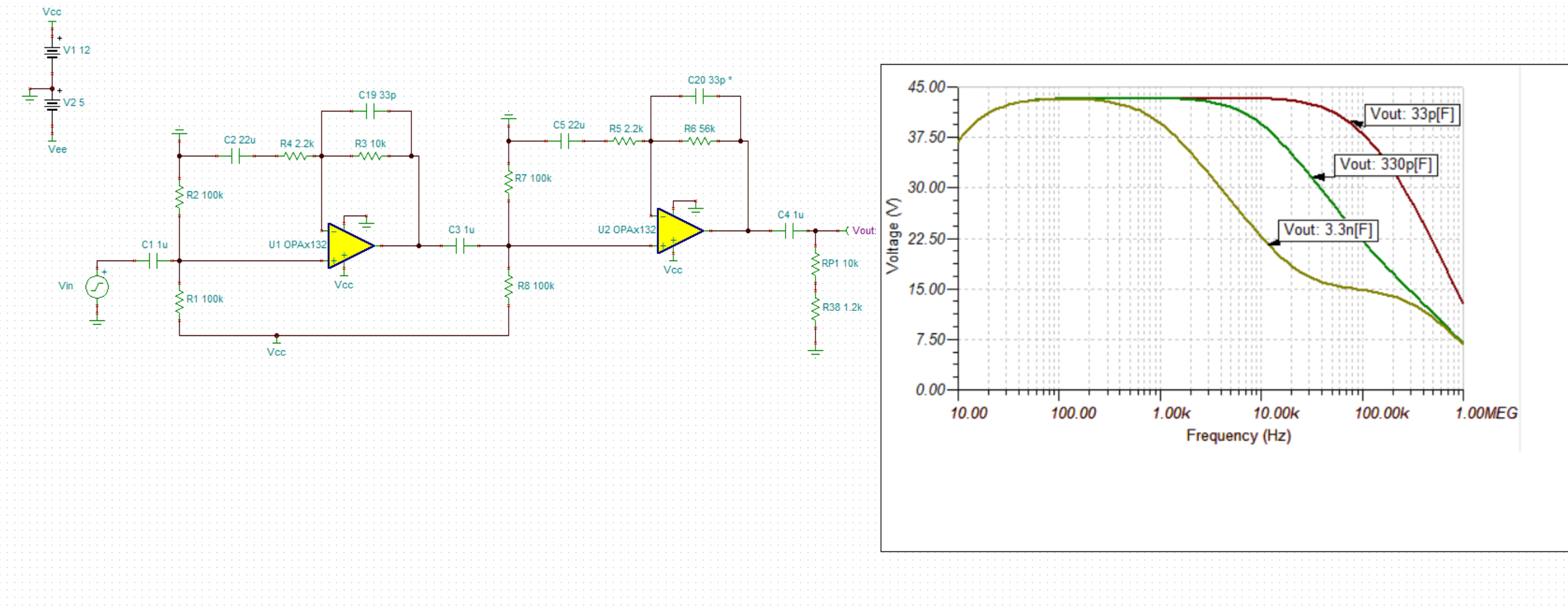
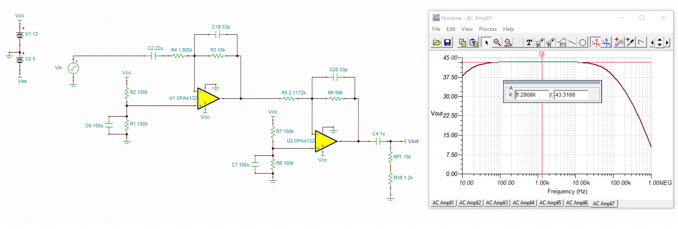
One suggestion would be to add a cap across R2 to GND in order to filter and noise coming in from the supply down to the non-inverting node, created by the voltage divider. Providing a low pass filter here would be good to get a nice clean signal for Vcm. It will mess up the gain and add distortion in this configuration however. I have provided an alternative idea shown below that filters the noise from the supply line on the non-inverting node. The capacitor is not loading the mic now and you gain the benefit of the low pass filtering at this node. This does however change the gain since the circuit is inverting. I have back calculated the resistor changes for R4 and R5 that would be needed to achieve the same gain in your circuit.
You can see below that the gain is 43.31dB which closely matches your desired gain. The input and output signals will still be in phase as well given the two inversions. Let me know if I can be of further assistance!
Best Regards,
Chris Featherstone
Thank you so much!
I rely on battery power, so I didn't think about power interference. If powered by a battery, can I leave my circuit? Or will interference still occur?
In your circuit, I am confused by the very large capacitance of the input capacitor. 22u is electrolytic only. And I would like to focus on WIMA MKP10 film capacitors with a capacity of 1-2.2u. Is it possible? My clients like the feed-through capacitors of this particular company.
Have I assembled the mixer correctly? Are the resistor values RP1, R19, R38 correct?
I apologize for bad english.
Gennadiy,
I have updated the Tina file with the complete circuit from your schematic below.
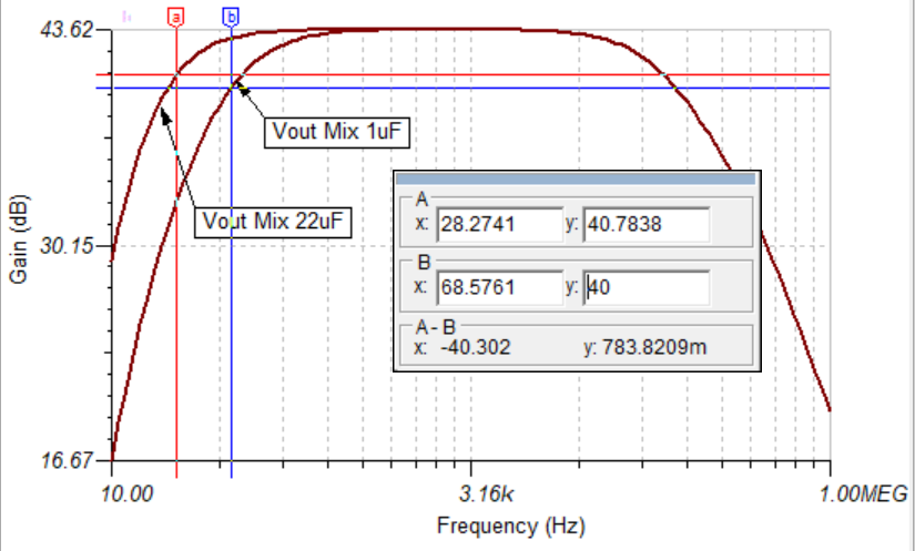
If you are operating on a battery and with low noise then your circuit is fine. The 22uF I got from your original circuit, unless I misread the value. See below. This could be adjusted however such that you can get a lower value for a film cap. The low corner frequency will change depending on the value that you choose. For example I have tested the overall system bandwidth with two values to show the difference.
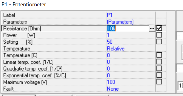
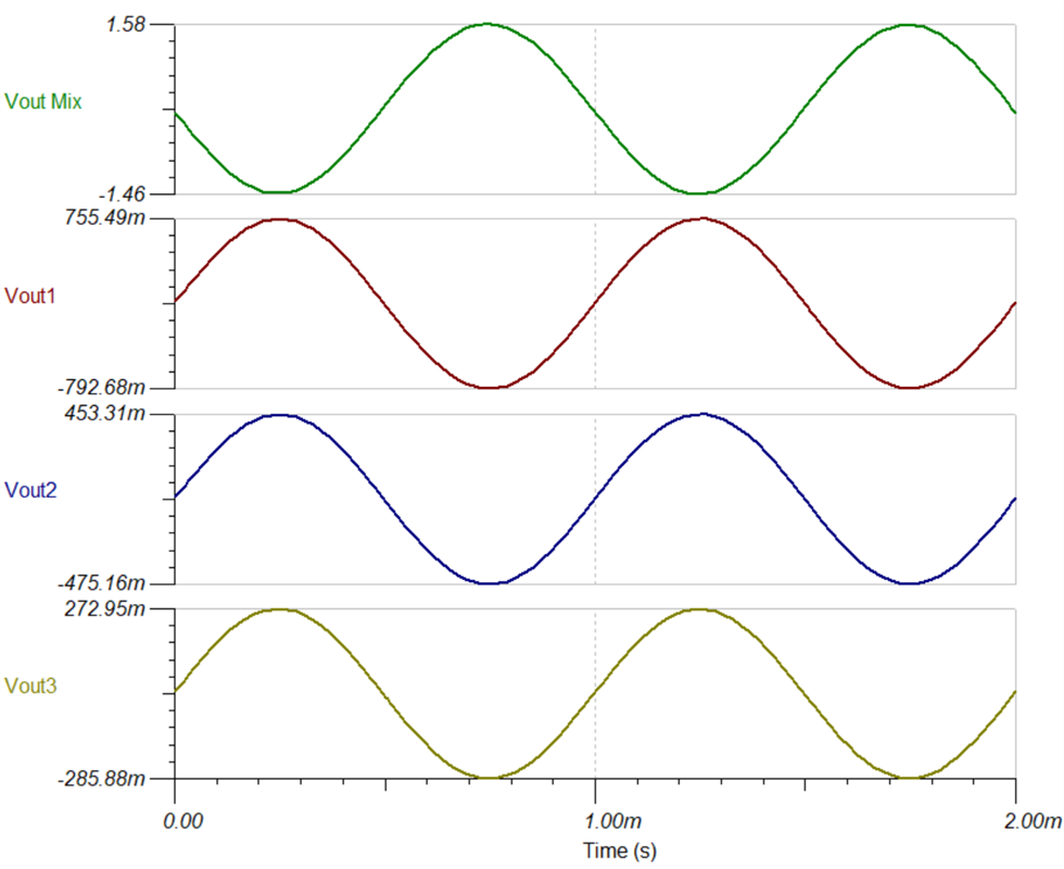
I have checked the circuit by varying the potentiometers such that each output prior to summing is of a different volume level. I did this by putting a different Setting percentage as shown below for each potentiometer. The circuit does appear to function with the desired function. RP1, R19 and R38 are correct for the desired function. R19 will prevent the output of the Op Amp from being loaded too much when the potentiometer is set to a low resistance value for example. R38 will prevent each output from being shorted together such that the volume control doesn't work.
I hope this helps!
Best Regards,
Chris Featherstone
Gennadiy,
The frequency response isn't showing for me on my last post. Hopefully you are able to see it. If not here is the image again.
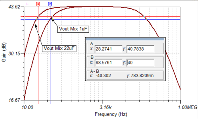
Best Regards,
Chris Featherstone
Thank you very, very much!
There was still a question about capacitors C2, C3, C4, C28, C29. Did I choose their capacity correctly? In my software there is no way to see the bandwidth.
Is the value of resistor R41 correct? Or maybe it should be increased to 100k? The next stage will be an equalizer or an optical compressor (the client will be able to choose for himself, depending on his situation).
The client also wants one balanced mic input and one balanced line input (I learned about this this morning). It would probably be possible to connect the INA1690 chip. Did I do the right thing? Are the XLR connections for Europe correct? Or should I swap pins 3 and 2.

Hey Gennadiy,
If it helps for analysis we offer Tina for free and it can be downloaded in this location:
https://www.ti.com/tool/TINA-TI
If you are interested in Tina and need assistance using it, I would be more than happy to assist.
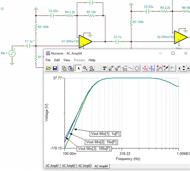
Great question on the caps. The dominating cap will be Caps C2 and C5 for the low end frequency cutoff. For example I have swept capacitor C1 with 3 values to show the difference in the low end with 1uF, 10uF, and 100uF. You can see below that it only affects the ultra low end in frequencies. That being said I believe the choice for caps C1, C3, C4, C28 and C29 are fine choices. It makes sense to control the low end cutoff with C2 and C5 as the dominating caps for the corner frequency as you have done. Depending on how low in frequency the customer would like to go you can adjust C2 and C5 according to their spec.
Cap C1 is being swept. This is indicated in the schematic with the * next to C1 1U shown below.
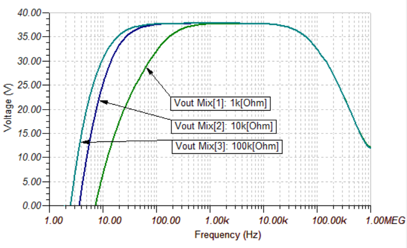
Varying resistor R41 shows the impact on the low end as well. 100k will be a good choice as to not load down the amplifier too much. You can see below that 100k will preserve the low end nicely.
I will respond in a new post for the balanced mic inputs. I will put together this input in the simulation shortly.
Best Regards,
Chris Featherstone
Gennadiy,
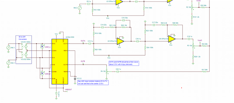
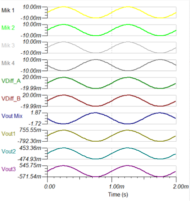
I have placed an INA1650 into the simulation for microphones 3 and 4 and they are summed into the other lines to the final output. The simulation is at the bottom of this post. I performed a single to differential conversion at the inputs in order to represent a differential mic input in simulation. The signals simulate fine as shown in the waveforms.
Best Regards,
Chris Featherstone
Thank you so much!
I am very, very grateful to you. Now I will order the first trial batch. I really hope everything works out well.
I didn't know that www.ti.com/.../TINA-TI is free. I used Easyeda, but of course there are no such features. The next thing I'm going to do is the equalizer. And it will be very good to have such opportunities.
Gennadiy,
No problem! Best of luck on your project and reach out if I can be of further assistance on Tina or the circuit!
Best Regards,
Chris Featherstone
Chris, I have now finished creating the printed circuit board and will be waiting for it to be brought from China. Thanks again for your advice!
I have now created a new question. Perhaps you can help me. I understand that you are busy. But if you have some time, please take a look at e2e.ti.com/.../equalizer-with-non-standard-frequencies.
Good luck and have a nice day!