This thread has been locked.

If you have a related question, please click the "Ask a related question" button in the top right corner. The newly created question will be automatically linked to this question.

TAS5613A: Different overcurrent behavior in different chip

Part Number: TAS5613A


Hi team,

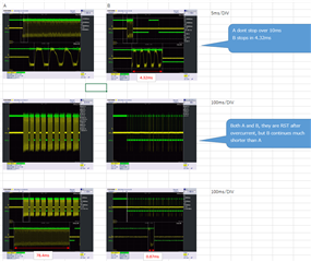
My customer have found different overcurrent behavior in different chip. Please see below waveforms to give me your thoughts about why there is difference.

And could you please teach me the detailed behavior of overcurrent.

Customer also want to know why Schottky diode is required when Rocp = 22kohm, which is written in Ioc of E.C.. What will happen without the Schottky?

Situation: PVDD = 24V, PBTL, Rocp = 30kohm (14A)

When overcurrent occurs, host sends RST to restart.

Waveforms - CH1(yellow): Output current, CH2(Green): SD

Best regards,

Hayashi

  • Hi Hayashi-san

    About the Schottky diode, if without that, large ground noise will affect the oc measurement result. so we add it to make sure most of the current flow back through the diode.

    About the delay about oc trigger, maybe the measurement method will affect the result.

    although u observed that the current already higher than the threshold, the actual current inside still have some margin to trigger the ocp.

    so the delay you measured maybe not that accurate.

    theoretically, this delay should be very short, however we haven't measured that before.

    thanks.

    Jesse

  • Hi Jesse,

    Understood about the Schottky.

    First of all, in the first question, let me confirm whether both behavior/waveform are correct  or not?

    Customer and I don't understand how the device reacts when the overcurrent event theoretically, so I don't figure out the different OC threshold leads different behavior.

    If customer are not able to understand the differencies, they can not control the system to react to fault events.

    Best regards,

    Hayashi

  • Hi Hayashi

    The mechanism of oc is something like there is a comparator inside of the circuit.

    and if the current is over the Ithres, then a signal will go to shutdown the device.

    Usually we measure the over current with shorting the output.

    So if you want to confirm the delay, it will better to short the output and measure the current wav, then confirm when the current over the Ithres, how long it take to shut down the device.

    thanks.

    Jesse

  • Hi Jesse,

    Let me add 3 questions.

    1) Effects of Schottky barrier diodes on outputs
    By adding a Schottky barrier to the output, the time to stop the output was extended to about 150ms to 160ms for both ICs that had a short OC time to stop the output and ICs that originally had a long OC time to stop the output.
    Is it correct to understand that the addition of the diode suppressed OC trigger malfunctions caused by noise and absorbed individual IC differences (susceptibility to noise)?

    2) Differences by IC lot
    We found that the IC from the lot starting with 0B tended to take shorter time to stop output than the IC from the lot starting with 8C.
    The time to stop output was shorter for ICs with lots starting with 0B than ICs with lots starting with 8C. (Such a trend was observed for several ICs, depending on the lot.)
    Is there any difference between lots starting with 8C and lots starting with 0B? (including the structure of die, bonding, etc.)

    3) Behavior of overcurrent protection circuit
    Customer understood that the mechanism to stop the output with overcurrent protection is to count up/count down depending on whether the output current exceeds the threshold value in the PWM cycle, and stop the output when the count reaches a predetermined number.
    I understood that the predetermined number of counts is 400k × 2.6m = 1040 counts, since the datasheet says OLPC 2.6ms at 400kHz.
    In reality, however, when the output current reaches the threshold value, the PWM is thinned out, so the countdown occurs in the cycle when the current is reduced by the thinning. Is this correct?

    Best regards,

    Hayashi

  • Hayashi

    Sorry for reply you late.

    1) Yes, as your understanding, the addition of the diode can avoid noise to trigger the oc. But i don't think it can absorb the individual IC difference for the oc trigger is decided by internal circuit.

    2) When you test different IC from different lot, are they using the same surround circuit? I mean you just change the IC instead of using different board for different IC.

    3) the trigger circuit is totally a analog circuit, there is no counting up or down. once the current overdue the threshold, there are no counting, it will shutdown immediately.

    thanks.

    Jesse

  • Hi Jesse,

    2) When you test different IC from different lot, are they using the same surround circuit? I mean you just change the IC instead of using different board for different IC.

    They actually use same board with different IC, then have seen different behavior.

    Overall, the different result is seen because of the variation of OC threshold, is my understanding correct?

    Best regards,

    Hayashi

  • Hi Hayashi

    Your understanding is right.

    thanks.

    Jesse