This thread has been locked.

If you have a related question, please click the "Ask a related question" button in the top right corner. The newly created question will be automatically linked to this question.

Equalizer with non-standard frequencies

Other Parts Discussed in Thread: OPA2132

Good afternoon. I need to create an equalizer with non-standard frequencies. That is, these frequencies are not spaced at the same intervals.

I found the app webench.ti.com/.../filter-type. But I couldn't figure out how to use it.

I would be very grateful if you show by example the calculation of such a filter for the middle position and for values of 80 and 16000 Hz. The maximum/minimum input and output frequencies are 20 - 20000 Hz.

 Thanks!

  • Hi Gennadiy,

    The filter tool shows some error on the beginning screen but you can ignore it and click "new design" in the upper right. This is another filter tool that I'm a fan of: http://sim.okawa-denshi.jp/en/OPttool.php

    What do you mean by "middle position"?

    Best regards,

    Jeff

  • What do you mean by "middle position"?

    I would like to see the calculation of any one filter from 250Hz to 12000Hz. I think that they are the same in terms of the calculation method.

    Thank you! It seems to be more simple. Could you show in practice how to calculate any of the filters?

    I have never created filters before and I am very afraid of making a mistake. OPA2132 are not cheap op amps. And you need a lot of them even for a test device.

  • The input impedance of such a circuit is R1 / 10. What value of R1 would you recommend?

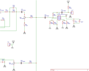
    The input signal will be taken from the mixer based on the OPA2132.

  • Hi Gennadiy,

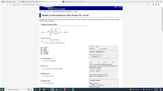
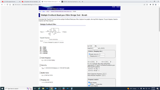
    Take note of the formulas on the page as they will vanish once you start doing calculations. First thing is to enter a center frequency, a Q factor (or a damping ratio but Q makes more sense here) and a gain. Press calculate at the bottom and something like this will appear:

    As you can see it gives us component values and a lot of characteristics that give a good starting point. If you scroll down you'll get a bode plot. Take note of the capacitor ratios on the right. We'd like the input impedance to be pretty high, so if we maintain the same capacitor ratio but make them smaller, we can increase the resistances.

    However this becomes less of an issue if the output impedance preceding this stage is very low. If I understand your diagram correctly, the output of the Panel_OPA2132 goes to the EQ stage correct? This means the input impedance doesn't have to be so high.

    As far as preventing damage, I'd simulate one EQ filter at a time to make sure you're getting the result you want; then simulate them in the same circuit like you have shown before prototyping or experimenting. As long as your voltage supply is safe and you are not providing inputs much higher than line level (2Vrms) you shouldn't have much risk for damage.

    Best regards,

    Jeff

  • Thank you! It seems to be more or less understood.

    OPA2132 goes to the EQ stage correct?

    Yes. Is it possible to set R1? For example, 30 kOhm (or should I choose another value?). And then do the calculation? Or can approximately the same input resistors be obtained only by selection?

    The power supply of the circuit is unipolar, from a 12V battery. Maximum, the input voltage can reach half the supply voltage (6V). Can it cause damage? Or is it better to put a limiter between the mixer and the EQ? If so, please advise the scheme of such a device. Thanks again!

  • Hi Gennadiy,

    Unfortunately this tool doesn't let you set a resistor and recalculate like that. That's why I mentioned taking note of the formulas, as once you have a starting point, you can work backwards to get a particular resistor value. 

    With a 12V supply, 6V is safe for the device. 

    Best regards,

    Jeff

  • Thank you!

    I'll try to calculate with formulas.

  • Please tell me what type of filter you need to use for the equalizer. Bessel or Butterworth?

  • Hi Gennadiy,

    Bessel and Butterworth provide their own trade offs. Bessel filters are very good at preserving group delay across the pass band but are not as selective. Butterworth filters can be very selective but don't have as good of a group delay response as you transition from the passband to the stopband. It's ultimately a design choice that is up to you, but in my opinion, I would use a Butterworth filter as phase response is generally less consequential than frequency selectivity in terms of what we end up hearing.

    Best regards,

    Jeff

  • Thank you!

    I will try to simulate both options.

  • Thanks again for your help.

    Now I'm waiting for a sample of the device. I hope everything will be alright with him.

    Good luck!