This thread has been locked.

If you have a related question, please click the "Ask a related question" button in the top right corner. The newly created question will be automatically linked to this question.

TLV320AIC3110: Playback PR Blocks problem

Part Number: TLV320AIC3110
Other Parts Discussed in Thread: TLV320AIC3120

Hello,

I can't make all PRB working. In fact, I am interested in the last one, PRB_P25 because of the "beep"

The clocks are provided by STM32F7 micro. The current settings are:

MCLK = 4.096kHz, BCLK = 512kHz, SR = 16kHz, Bits = 16

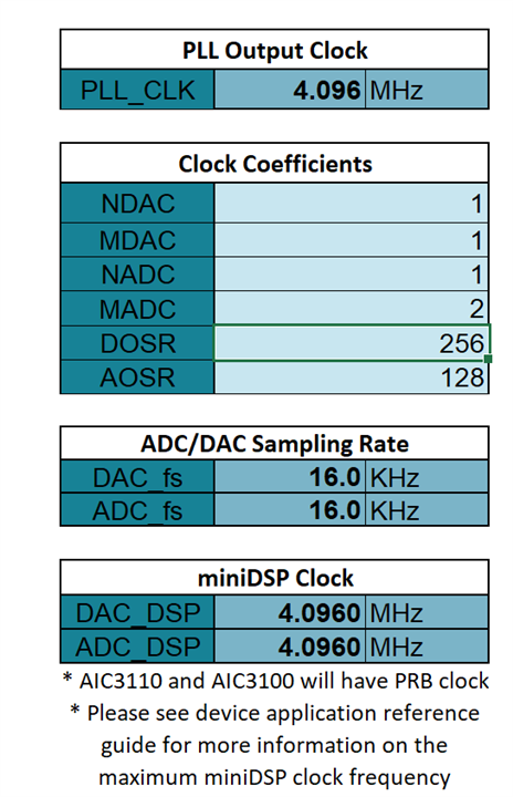
PLL off, NADC = 1,MADC = 2, NDAC = 1,MDAC = 2, AOSR = DOSR =  128

The PRB's in the yellow rows are not working. The output signal looks like modulated, as the DAC and the PRB runs on different clocks.

I have checked with bigger OSR with no success:

PLL off, NADC = 1,MADC = 1, NDAC = 1,MDAC = 1, AOSR = DOSR =  256

I have checked with PLL, but this produce incredible noise on the output:

P=1, R=1, J=24, N=1 or 48, M = 48 or 1, OSR = 128

I have ACEV board with TLV320AIC3120 and there all kind of settings works well or as expected if they are wrong. But our design is with AIC3110 and I have not EVM.

Can I have advise on this, please? I have feeling that the Resource Class is somehow related.

Thank you.

  • Hi,

    Your configuration does not give he correct sampling which likely causes noise.

    Please use the following settings with PLL enable.

    Or this with PLL disable:

    And give it a try.

    Regards.

  • Hello ,

    Thanks for your reply. But still it doesn't work with PRB_P2, 3, 10, 24, and 25

  • {0x00,0x00}; //Page sel
    {0x01,0x01}; //s/w reset
    {0x04,0x00}; //PLL_clkin
    {0x05,0x21}; //PLL On/Off, P , R
    {0x06,0x30}; // PLL J
    {0x07,0x00}; //PLL D MSB
    {0x08,0x00}; //PLL D LSB

    {0x1B,0x00}; //I2S Mode

    {0x0B,0x81}; //DAC NDAC
    {0x0C,0x81}; //DAC MDAC
    {0x0D,0x01}; //DOSR(9:8)
    {0x0E,0x00}; //DOSR(7:0)

    {0x12,0x81}; //ADC NDAC
    {0x13,0x82}; //ADC MDAC
    {0x14,0x80}; //AOSR

    {0x74,0x00}; //DAC volume control thru pin
    {0x44,0x00}; //DAC => DRC
    {0x41,0x00}; //DAC gain left
    {0x42,0x00}; //DAC gain right

    {0x00,0x01}; //page 1 is selected
    {0x21,0x4E}; //De-pop
    {0x1F,0xD6}; //HPL and HPR power and CM
    {0x23,0x44}; //LDAC routed to HPL, RDAC routed to HPR
    {0x28,0x07}; //HPL Gain
    {0x29,0x07}; //HPR Gain
    {0x24,0x00}; //HP ATT
    {0x25,0x00}; //HP ATT

    {0x30,0x40}; //MICPGA P = MIC 10k
    {0x31,0x40}; //MICPGA M - CM 10k

    {0x00,0x00}; //page 0 is selected
    {0x3C,0x19}; //select DAC PRB_P25 & enable adaptive filter
    {0x00,0x08};
    {0x01,0x04}; //DAC Adaptive Filtering Control, buffers are not switched at the next frame

    {0x00,0x00}; // Page sel
    {0x3F,0xD6}; //POWERUP DAC left and right channels (soft step disable)
    {0x40,0x00}; //UNMUTE DAC left and right channels

    {0x51,0x80}; //POWERUP ADC channel
    {0x52,0x00}; //UNMUTE ADC channel

    {0x00,0x01}; //page 1 is selected

    {0x2B,0x1C}; //Unmute Class-D Right
    {0x20,0x46}; //Power-up Class-D Right only
    {0x26,0x7F}; //Class-D Left volume muted
    {0x27,0x17}; //Class-D Right volume to -14dB

    {0x2F,0x00}; //On PGA with gain 0dB

  • This is the output with 2600Hz analogue wave on the input and PRB_P25.

    All looks good with any PRB_P except  2, 3, 10, 24 and 25.

  • Hi,

    Let's use the PLL setting, so set the following:

    {0x04,0x03}; 

    {0x05,0xA1};

    {0x0B,0x82}; 
    {0x0C,0x88}; 
    {0x0D,0x01}; 
    {0x0E,0x80}; 

    {0x12,0x86}; 
    {0x13,0x88}; 
    {0x14,0x80}; 

    Are you monitoring at the HP output and it's the correct waveform for other PRB without PLL?

    So is this 2.6KHz signal from ADC or from the host?

    Regards.

  • Hello Juan,

    Yes, I am monitoring HPL output through additional analog amplifier (TDA2005 to be precise).

    Without PLL, the output looks right for all PRB_P  except  2, 3, 10, 24 and 25.

    With any kind of PLL there is a (white?, FM?) noise on the output and very weak signal. Right now I am trying different PLL settings

    Here are the results without PLL for PRB_B18 and PRB_B25. Signal 2500Hz, ADC-DAC loopback.

    {0x00,0x00}; //Page sel
    {0x01,0x01}; //s/w reset
    {0x04,0x00}; //PLL_clkin
    {0x05,0x21}; //PLL On/Off, P , R
    {0x06,0x30}; // PLL J
    {0x07,0x00}; //PLL D MSB
    {0x08,0x00}; //PLL D LSB

    {0x1B,0x00}; //I2S Mode

    {0x0B,0x81}; //DAC NDAC
    {0x0C,0x81}; //DAC MDAC
    {0x0D,0x01}; //DOSR(9:8)
    {0x0E,0x00}; //DOSR(7:0)

    {0x12,0x81}; //ADC NDAC
    {0x13,0x82}; //ADC MDAC
    {0x14,0x80}; //AOSR

    PRB_P18

    PRB_P25

    PRB_P25_AC

    The micro also can generate I2S sine wave, but the frequency calculations are no exactly right. Anyway, the result is the same with I2S sine wave.

  • Hello Juan,

    This is what happens with PLL running, PRB_P1 and I2S wave of 1034Hz :

    {0x00,0x00}; //Page sel
    {0x01,0x01}; //s/w reset
    {0x04,0x00}; //PLL_clkin
    {0x05,0xA1}; //PLL On/Off, P , R
    {0x06,0x30}; // PLL J
    {0x07,0x00}; //PLL D MSB
    {0x08,0x00}; //PLL D LSB

    {0x1B,0x00}; //I2S Mode

    {0x0B,0x82}; //DAC NDAC
    {0x0C,0x88}; //DAC MDAC
    {0x0D,0x01}; //DOSR(9:8)
    {0x0E,0x80}; //DOSR(7:0)

    {0x12,0x86}; //ADC NDAC
    {0x13,0x88}; //ADC MDAC
    {0x14,0x80}; //AOSR

    The above settings should give the next clocks, as you recommended in your first answer:

    MCLK 4096000

    CODEC_CLKIN 98304000

    DAC_CLK 49152000
    DAC_MOD_CLK 6144000
    DAC_fS 16000

    ADC_CLK 16384000
    ADC_MOD_CLK 2048000
    ADC_fS 16000

    The result is hisssssssssssss:

  • For the PLL case, you need to set {0x04,0x03} instead of {0x04,0x00}.

  • Thank you very much, Juan. It works now.

    Let’s summarize:

    1. The PR blocks with higher resource class require higher clock. Master clock of 4096kHz can’t run properly some of them. I found this in another datasheet: MDAC * DOSR / 32 ≥ RC, but this is not mentioned in the datasheet of AIC3110.
    1. The input without PLL is MCLK, the input with PLL is DI. This is not quite clear for me, but it works, ok:

    Now all looks good without DRC. I will check with DRC, because there is a limit of the DAC_CLK for the DRC.

    Thanks again.

  • Good to know.

    On the DIN question, this is only applicable to system that is not using the DAC path, DIN can be used as clock input.

    Regards.