This thread has been locked.

If you have a related question, please click the "Ask a related question" button in the top right corner. The newly created question will be automatically linked to this question.

Limiter

Other Parts Discussed in Thread: OPA2132, TL972

Hello!
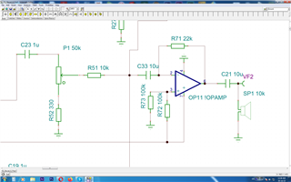
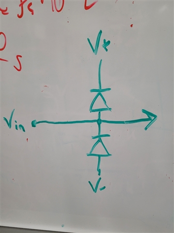
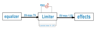
I faced such problem. The maximum output voltage from the equalizer can reach 7V. Further, this voltage is applied to the blocks of various effects. The input voltage of these blocks is in the range from 1.1V to 2.5V. Is it possible to use a limiter to limit the voltage? It is required that it has a tunable response range and an indication of reaching the threshold value. Perhaps you have such a scheme?

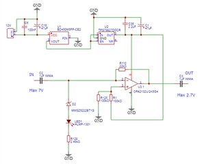
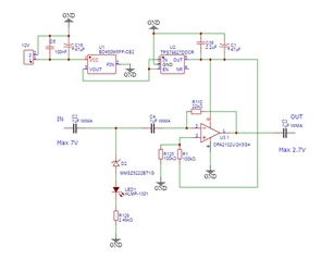
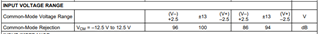
 Main battery 12v. Power supply unipolar.

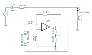
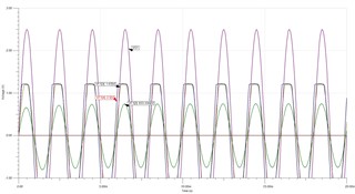
Perhaps there is such a scheme on the operational amplifier? I would like to have as few THDs as possible. Such limiters are used several times in my device.
Thank you so much for everything! Good luck with everything!

  • Hello Gennadiy, 

    It is possible to use a limiter to control the dynamic range of a signal, and therefore limit the voltage. Additionally, limiters offer a tunable response, in which you can adjust how the limiter reacts to an incoming signal by changing its attack time, release time, and threshold. In general, limiters use high compression ratios and quick attack times to deny any transient signal from crossing the threshold, so you could strictly tame incoming signal to a maximum value.

    Looking on our website, I found the TPA3140D2 power level limiter and unclipped automatic gain limiter device. Perhaps this could assist you in your design, and I would recommend using the unclipped automatic gain limiter feature. Using this product you could tune the limiter response, as well as attach an LED to the “LIMTHRES” pin after it has been configured to visually observe an indication of reaching the threshold value. Since the effects chain requires a minimum voltage of 1.1V, if the signal output by the limiter is lower than 1.1V you could apply some make-up gain to bring that to the appropriate level. 

    Although limiters or other dynamic control processors can be handy, they will reduce the dynamic range of your signal and could introduce unwanted signal artifacts. Since your equalizer outputs a maximum of 7V, I would recommend trying a gain reduction buffer and skip the use of a limiter. Here you could cap the maximum voltage level of your signal as well as retain the dynamic range.

    Best regards, 

    Alec Greene

  • Thanks for the detailed answer!

    That's why I asked the question, that I would not like to use dynamic signal processing. I'm looking for some simple solution. For example, if the question was about limiting 5V, it would be enough to simply pass the signal through a repeater created on an operational amplifier with the same power supply (5V). In this case, the signal could not physically exceed the supply voltage.

    But such a solution to the problem is not possible if you want to limit the signal to a level between one and two volts. Perhaps such a circuit can be created on a transistor? Or there are operational amplifiers for such a low supply voltage?

    I now use OPA2132 in all parts of my device. Therefore, I would like to have something with a low THD (below 0.1). It is desirable to have a THD of approximately 0.01. If this is of course possible.

  • Hi Gennadiy,

    The OPA2132 already has very low THDN (0.00008%). Do you mean the limiter device needs to have this kind of distortion performance also? A second question would be do you intend to clip anything above 2.5Vrms or do you want to reduce the 7Vrms loudest signal to 2.5Vrms? If you're wanting to clip you could bias the signal to 2.5Vrms and then clip it against a 5V supplied op amp. I do agree with Alec that the simplest solution is to just attenuate the signal coming out of the EQ stage with either an <1 gain op amp or even a simple voltage divider.

    Best regards,

    Jeff

  • Thank you! I apologize for my bad english.

    I just want to cut the signal. And of course I want to keep THD as low as possible. There is a mixer in front of the equalizer. It has signal attenuation controls. But, when connecting multiple inputs, the signal may exceed 7V before it is reduced. And this will cause destruction of the effects board.

    This requires an additional device that will act as a fuse and limit the voltage to a predetermined value. When this happens, the LED should light up. It will tell the sound engineer about the need to reduce the signal at the output of the mixer to the required value.

    One of the effects units has a maximum voltage of 2.5V VP-P (peak to peak).

    The second block has a maximum voltage of 1.2-1.5V. This block is still in development and I don't know the exact value of the maximum voltage.

    FX units have a THD of 0.015%

    The whole device has a 12V unipolar power supply.

  • Hi Genndaiy,

    No worries about the english. So to clarify you want to clip any signal the passes over 7V and this will trigger an LED indicator. Understand that this clipping will cause very bad THD but that's intentional as this is to protect the circuit. Afterwards you want that signal reduced to a 2.5Vpp signal to go into the FX stage?

    An op amp comparator would be an easy way to trigger this LED, using the supply rail with a divider to generate a 7V reference. The same signal could open a transistor with a resistor to ground to pull the signal down away from the FX stage. You could also use clamping diodes to keep the signal from reaching 7V separately from the comparator. However I still believe the simplest way is just to provide fixed attenuation to output of the EQ stage such that the loudest signal is about 2.5Vrms. 7V is quite a lot and as you're noticing, audio stages aren't equipped to handle that.

    Best regards,

    Jeff

  • Perhaps I do not quite understand you or I cannot explain correctly.

    I will try to explain again. Each mic preamp output of the mixer can deliver about 2.5V maximum. If only one input is used, that's good. But if you use, for example, all six possible, then the signal will be limited to only half the supply voltage. At maximum battery charge, this is seven volts. Further, this signal will go to the input of the equalizer and, again, 7V will be obtained at its output. When the person who controls the mixing console hears a creepy clipped signal, he will reduce the signal that goes to the input of the equalizer and beyond. But during this time, the effect block circuit will be destroyed. I need a circuit that will not physically be able to deliver more than 2.5v peak to peak. But capable of receiving a signal of at least 7.5V without harm to itself. This will protect the effects unit while the DJ manually lowers the volume.

    Afterwards you want that signal reduced to a 2.5Vpp signal to go into the FX stage?

    The signal will have to be reduced by a human. Turning the gain knob down.

    If the signal exceeds 2.5V very much, then it can be heard with the ears. If the signal will exceed by a small value, it is more reliable to use an LED.

  • Hi Gennadiy,

    I think I understand better and I believe clamping diodes would be the best way to go. Using an op amp to bias the signal to 6V and then clamping a +-2.5Vpp range on the output. Afterwards you can AC couple to remove DC and go into the FX stage. Before this op amp (while the signal can still be 7V) use a comparator to drive your LED indicator. That's the best advise I can give on this design.

    Best regards,

    Jeff 

  • Thank you!

    What are clamping diodes? Will they degrade the performance of the audio circuit?

    Could you provide an example of the circuit you advise? I'm not so well versed in this that I would come up with such a scheme myself.

    Thanks again!

  • This is the output stage of the equalizer.

  • I checked the documentation for the OPA2132 again and found that this chip can run at a minimum of 2.5V. Perhaps then it is possible to make such a scheme?

    If I'm right and it will work stably, please tell me what to do with pin 4 (NR). Now I have left it free. But the documentation shows a capacitor. But its capacity and type are not specified.

    Will the indication work in this case and will it introduce additional noise into the audio path?

    I installed the first LDO, since the voltage of a fully charged battery can theoretically exceed 15V.

  • Hi Gennadiy,

    Here's an example of clamping diodes:

    When Vin reaches V+ the diode conducts and draws voltage away from the intended signal path. Likewise for V-. However since you care more about overvoltage than undervoltage, the zener diode you have above is probably a better solution and directly drives the LED.

    I'd put another coupling cap before the op amp inputs but after the diode path to aid in coupling so that pin 3 doesn't fight against the input. I'm not an expert on the U2 regulator since it doesn't belong to the audio team. To get the best help on the NR question, I would make a new thread that lists the TPS79927 as the query. 

    Best regards,

    Jeff

  • Is that right?

    My concern is whether the op-amp will be stable at such a low supply voltage.

  • Hi Gennadiy,

    The common mode voltage range of the part is below:

    2.7V is too low of a supply. But I think the architecture is the right direction.

    Best regards,

    Jeff

  • Thank you!

    I looked at the characteristics of some other chips. If I understand you correctly, then TL972 should be fine (if you change the power supply to 2.85V).

    Perhaps you can recommend another chip with better specs? I don't know how to find such a chip myself.

  • Hi Gennadiy,

    I should have elaborated. If your supply is 2.7V you will experience op amp clipping when the input is higher than 0.2V. Your supply needs to be twice that of your maximum swing. If you expect a maximum 2.5V signal (zener diode conducts at this voltage), you need at least a 5V supply.

    This link will take you to our audio op amps: https://www.ti.com/amplifier-circuit/op-amps/audio/products.html

    From there you can use the available filters to meet your design constraints, such as supply voltages.

    Best regards,

    Jeff

  • It seems I have found a solution.

    Please tell me until the limiter reaches the trigger mode, THD=0 ?

    How to connect this op amp to a battery (single supply)?

    How can I make an indication that the limiter has entered limit mode?

    Thank you!

  • Hi Gennadiy,

    THD is not going to be exactly 0 as there will be some introduced by the op amp. For single supply connect the positive pin to the positive battery and the negative to ground. Use a capacitor to ground (0.1uF is fine) to decouple noise from the power supply. I would create an LED indicator in parallel between the diodes utilizing the breakdown voltage of the zener diodes to create a path to light the LED. 

    Best regards,

    Jeff